Building
a 2-element Tape Measure
Yagi
During
the March 22, 2018 meeting, Dave Joseph W1AMX discussed how to
construct a simple 2-element direction-finding yagi for 2 meters. The
antenna can be made with about $12 in materials, all of which are
readily sourced at the local hardware store, and common
hand tools.
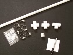
Parts List
- 9 ½
inches of ½
inch schedule 40 PVC pipe
- 1-½
inch schedule 40 cross connector
- 1-½
inch schedule 40 T-connector
- 1-½
inch schedule 50 cap
- 1
inexpensive tape measure (a 1 inch wide tape is recommended)
- 4
feet of coax cable with a connector on one end (UHF, BNC, SMA, etc.)
and the other end prepared for soldering
- 4
#12 (11/16 inch to 1 1/4 inch) hose clamps
- 5
inch piece of solid wire for hairpin tuning component (14 to
18 gauge will work)
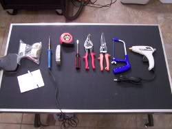
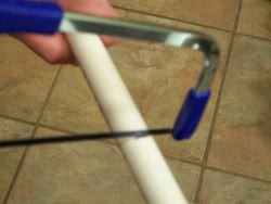
Tools
required
- Hacksaw
or PVC pipe cutter
- Soldering
iron or gun
- PVC
cement
- Electronic
solder
- Wire
cutter
- Hot
glue gun
- Tape
measure
- Tin
snips
- Black
indelible marker
- Metal
file
- Flat
blade screw driver or 5/16 inch nut driver (to tighten hose clamps)
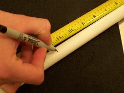
Step
1
Cut a
3 inch length of PVC pipe, and another that's 6 1/2 inches. The
3" length will be used to form the boom between the director and driven
element, and the 6 1/2" pipe will be used to form the handle, so you
can hold the antenna from the rear. Optionally, you may use an elbow to
angle the handle downward, but this depends on preference. Before
cutting the
pipe, measure and mark the length using a black indelible
marker.
Step
2
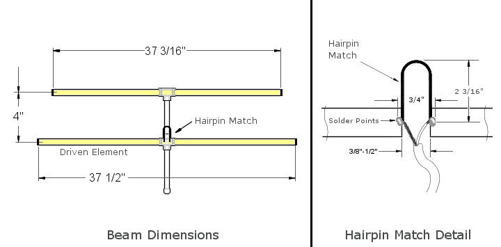
Cut
two lengths of tape measure to 18 5/8", which will be used for the
driven element, and another length of tape measure to 37 3/16", which
will be used for the director. Once cut, round off the corners of the
outside edges of the tape measure elements and cover them with
electrical tape, for safety. Then, sand and tin the other ends of the
driven elements, so it will make good electrical contact with the
feedline.
Step
3
The
time to tin the driven elements is BEFORE you connect them to the PVC
pipe, so the extra heat required to do so won't melt the plastic
pipe. Next, form the 5" wire into a "U" shape, with the two
legs
about 3/4" apart. Tin the ends of the hairpin to make it easier for
soldering later.
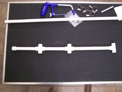
Step
4
At
this time you can pre-assemble the PVC boom, connecting the cross and
T, which will support the tape elements. PVC glue is not required,
since the pipe will press in securely to the fittings, but you can use
it if you choose to. When assembled, the cross and T will be 4 inches
center to center.
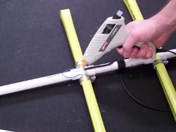
Step
5
Finally, use the stainless steel hose clamps to secure the tape measure
elements to PVC fittings as shown in the diagram.
More information about this, and other RDF
projects can be found at the
links below:
Dave
W1AMX also calculated measurements for the same antenna, but for use on
440 MHz. See below:
441
MHz 2 Element Yagi
Numbers are rounded off for ease in measurement.
No hairpin match needed.
Driven: 2 X @ 6.5"
Director: 11.70"
Spacing: 3.3"
Forward Gain: 3.78 dBd (7.112 X input power)
Front to Back: 8.52 dB
Calculated SWR @ 441 MHz: 1.07:1
1.5:1 VSWR Bandwidth: 20.053 MHz.
2.0:1 VSWR Bandwidth: 39.411 MHz.
Be sure to keep the spacing between the driven elements to about
1/4"-3/8".
HT
Tricks for Radio Direction
Finding
Use 'Body Shield/Fade' to get fade on
signal. Direction to
travel will be behind you.
When the null gets shallow..use one, some or all of the following with
'Body Shield/Fade' technique...
- Rotate radio 90 degrees for ~20 dB attenuation.
- Slip tin foil 'glove' over antenna.
- Radio in VFO mode - tune 5 kHz off frequency.
- Use paper clip for antenna.
If direction suddenly changes bearing - you've been following a
reflection.
Try to stay away from metallic objects (fences/buildings etc.)
If
no null disconnect antenna and look for signal using body. If
signal found - you may have 'arrived'. Start looking around.
Easy Loop Design
Here's
an easy method to make a loop for any frequency, courtesey of Dave
Joseph W1AMX. You'll need some 75-ohm coax to make a
transformer
to match to 50 ohms.
VHF Loop (146 MHz)
Length of wire/tubing = 1005/146=82.603"
Loop diameter will be: 26.31" - or -
A square with 20.65" sides. Feed square at one corner.
Use
RG-59 cable for matching transformer. Length will be the same
as one
side of loop (or 1/4 the total length of wire/tubing), minus the
velocity factor. i.e. 20.65" X .66 (velocity factor) = 13.63"
-
that's the length of your 75-ohm cable.
Use your favorite connector at end of 75-ohm cable to connect a 50 ohm
jumper to the radio. (BNC, UHF, etc.)
UHF Loop (445 MHz)
Length of wire/tubing = 1005/445=27.1"
Loop diameter will be: 8.63" - or -
A square with 6.775" per sides. Feed square at one corner.
Use
RG-59 cable for matching transformer. Length will be the same as one
side of loop (or 1/4 the total length of wire/tubing), minus the
velocity factor. i.e. 27.1"/4 = 6.775" X .66 (v/f example) =
4.472" -
that's the length of your 75-ohm cable. |
 |
Use
your favorite connector at end of 75-ohm cable to connect a 50 ohm
jumper to the radio. (BNC, UHF, etc.)
With
either loop design, an insulated square/rectangle with screws to mount
loop ends and holes to ty-wrap the coax to works well. Then some kind
of handle to that.
Use 1005/F(MHz) plus 1/4 of that for 75 ohm matching cable (+velocity
factor reduction) for any frequency you want.
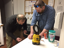
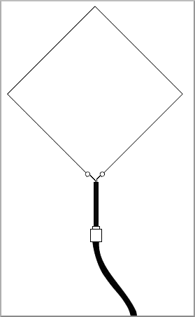
Building
a 2 meter Copper Dipole
Recently, we built one of the
K1RQG-designed 2m copper dipoles, and
construction is quite simple. All that's required is some 1/2" M Series
copper pipe, a small piece of PVC, some tees and end caps, and a
chassis-mount PL259 connector (to connect the coax). Its possible to
omit this and solder a split piece of coax directly to the antenna, but
for durability purposes, its recommended to use the
connector.
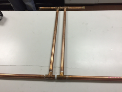
All material is 1/2" M Series copper pipe, except 1/2" X 1 1/4" PVC
(noted).
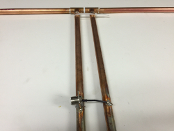
The tees are 1/4" apart after assembly.
The 18 1/2" subsections are 2" apart C/L to C/L.
Feedline is fastened (52 ohm coax) to the points A and B on the 18
1/2"sections.
Materials
needed:
10' of 1/2" M Series copper pipe
4 tees
4 caps
1/2" OD X 1 1/4" PVC pipe
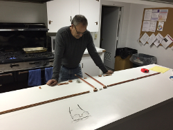
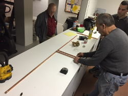
After
cutting the pipe to the lengths shown in the diagram, lay it out
on a large, flat surface, and fit it together. Its recommended,
however, to leave some extra length on the 38 1/2" sections
(the
two longest sections), in case the material is needed during tuning.
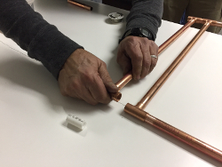
Once everything fits up nice, sand both ends of each joint with either
a 3M pad or fine grit sandpaper to prep it for soldering.
When
you're satisfided with the fitment, sweat the joints, and don't forget
to put the PVC spacer in place before soldering. Once this is complete,
attach the PL259 connector, as shown (above right). Now its time to
attach some coax and hook it up to an analyzer for final tuning. If
trimming is required, make the cuts as needed and solder on the end
caps. Finally, mount it up on a mast and begin transmitting.
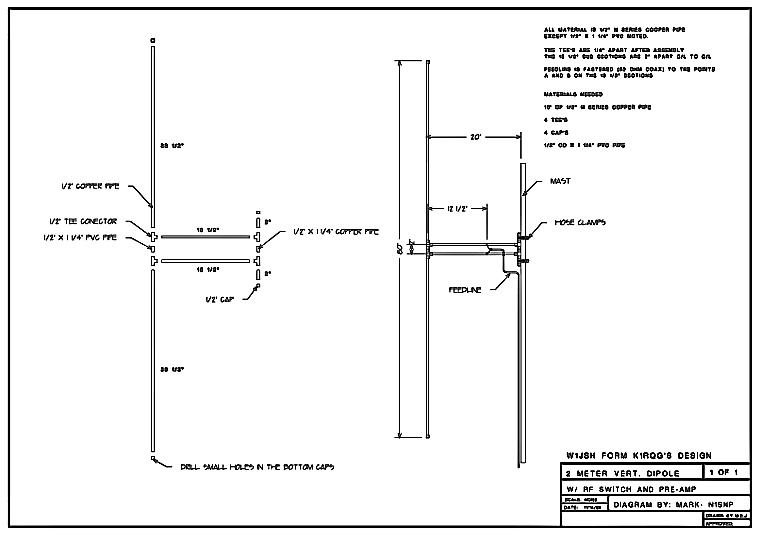
Click
here to download a high
quality PDF of the diagram shown above.
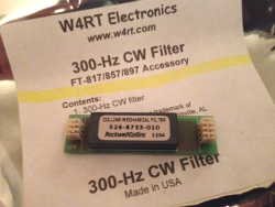
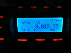
Installing
Optional Filters in
the Yaesu FT 857
Recently I decided to upgrade my Yaesu FT
857d field radio with
accessory filters (available through W4RT Electronics).
The ones I opted for are the 300-Hz (for CW) and 2.3-kHz (for
ssb)
Rockwell Collins mechanical filters. Installation is relatively easy,
but there are a few things to look out for.
The first step is
to disconnect any power source, and then to remove any mobile brackets
(if used). Next, we'll remove the 7 screws that attach the top cover (4
on the sides and 3 on top). Be sure not to unscrew the speaker screws,
as this is unnecessary. Once the screws are out, the top cover
slides off in the direction of the faceplate. The first thing
to
be careful of is not to damage the speaker wire, which will still be
connected. This wire can be detached from the board, but it
should be long enough to be able to set the cover on its side
and
out of the way.
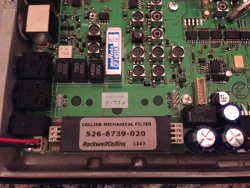
The
filters plug into the front right of the main board (if looking at it
from the control head). The spaces on the board are labeled FIL1 and
FIL2 respectively, allowing up to two filters to be installed at any
given time.
If you look closely at the filter slot, you'll
notice that on one side (LHS) there are 3 pins, and on the other side
(RHS), there are 4. When the filter is oriented properly, these should
line up perfectly with the female receptacles on the filter. Simply
align the filter (writing side up), and press into place. Press it
gently, however, to be sure not to bend any of the pins.
At this
point, your work is almost done. Slide the cover back in place, secure
it with the 7 screws, and reconnect to a power source. There's one more
step involved to begin using your filters. Press the B button (in Multi
Function Row 'n') to activate the optional filter installed in FIL1 (in
my case this was the ssb filter), and Press C to activate the filter
installed in FIL2. In some cases, you may have to change the setting in
Menu Mode No-086 to "FIL1" or "FIL2" as well to activate one or the
other.
After doing some preliminary tests, I'm astounded by
the performance of these. The CW filter, especially, makes a huge
difference. It has excellent frequency response, with very sharp
skirts, and no noticeable distortion.
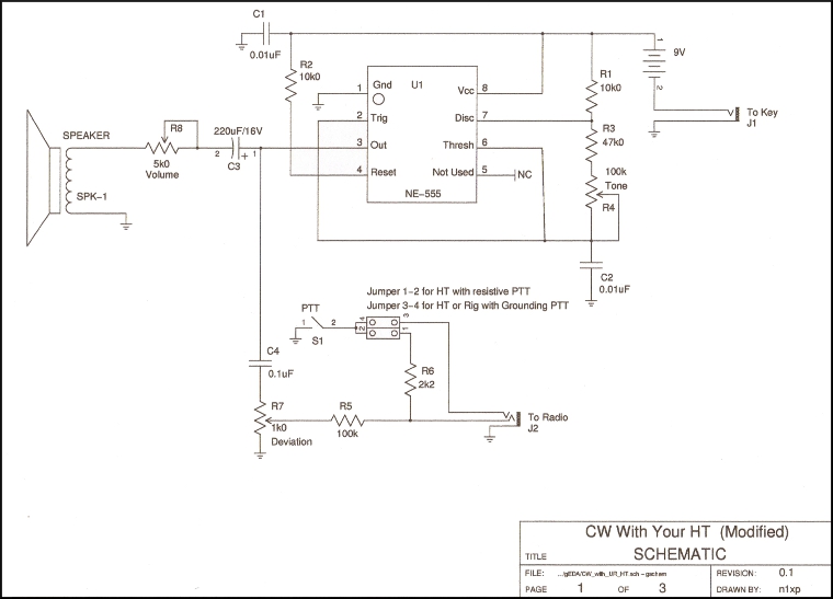
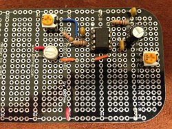
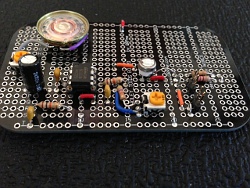
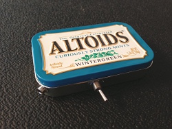
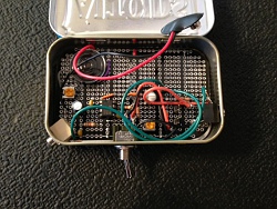
CW
With Your HT
Our CW With Your HT project is to
build a simple
device
that can be used with any handheld tranceiver to send modulated CW. It
is basically an audio oscillator and keying circuit which acts as an
interface between a cw key and a handheld radio. Modulated CW is
nothing more than audio tones keyed on and off and fed to your
transceiver's audio jack. The circuit design, including speaker and 9V
battery are small enough to fit inside an Altoids tin, or similar
enclosure, so it can easily fit in your pocket or be stowed with your
HT. Please find the schematics below, (drawn by Roger Pience, N1XP), as
well as a detailed parts list. As we build these over the next several
weeks, we'll post images of the construction process.
Parts
List
R1,
R2
R3
R4
R5
R6
R7
R8
C1, C2
C3
C4
U1
J1
J2
SPK-1
S1 |
10k0
/
1/4W Resistor (10,000 Ohms, Brown, Black, Orange)
47k0 / 1/4W Resistor (47,000 Ohms, Yellow, Violet, Orange)
100k Potentiometer (100,000 Ohms, Marked 104)
100k / 1/4W Resistor (100,000 Ohms, Brown, Black, Yellow)
2k2 / 1/4W Resistor (2,200 Ohms, Red, Red, Red)
1k0 Potentiometer (1,000 Ohms, Marked 102)
5k0 Potentiometer (5,000 Ohms, Marked 502)
0.01 uF / 50V Capacitor (Marked 103)
220 uF / 16V Electrolytic Capacitor
0.1 uF / 50V Capacitor (Marked 104)
NE-555 Integrated Circuit
3.5mm phone jack, mono
3.5mm phone jack, stereo
Speaker, 7 Ohm, 22mm-round
Switch SPST |
Additional Parts:
Bread Board or Holey-Toids Board (available at QRPme.com)
Enclosure
Battery Leads
8-pin IC Socket
Reference:
Circuit
Diagram (Image)
Carbon Composition Trimmer Potentiometers
Aluminum Electrolytic Capacitors |
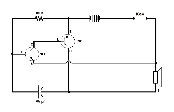
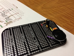
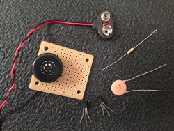
Building
a Miniature Code
Practice Oscillator
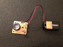
At
November's club meeting, Roger Pience N1XP, supplied kits of his own
design, and helped members build miniature code practice oscillators.
The kits are relatively easy to build and only require a battery
connector, 100k resistor, .50 uF capacitor, a couple of transistors,
and a small solderable bread board. It's also recommended that you
include a couple of leads or posts to attach a straight key.
Parts List
- 9V
Battery Connector
- 100k
Resistor
- .50 uF
capacitor
- 3904
Transistor
- 3906
Transistor
- Bread
Board
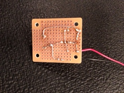
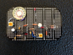
If
you look at the picture of the underside of the board, you'll see that
we also added some wire to complete the circuit, however most of the
contacts can be made by using the leads of the individual components,
bent over and soldered in the appropriate place. The best way to start
is by positioning a few components on the board, pushing their leads
through, and soldering them to the board, leaving their leads long. As
you add components, simply fold the leads over the back side and begin
to form the circuit, then do a final solder, adding wire where
necessary, and trim the excess material. After you complete this, plug
in a battery and a key, and you'll be making sound!
If you're interested in a kit,
complete with all the parts necessary,
please contact Roger Pience at: xp@n1xp.com
A
Band-Pass Filter for Field
Day
Field Day, for multiple transmitter
categories, presents interference
problems not normally associated with single-station setups. Unwanted
harmonics and receiver blockage are not only a nuissance, but can
potentially cause damage to your receiver as well. The solution are
these relatively inexpensive band-pass filters, which provide for
higher-power handling, increased reliability and
greater frequency attenuation than other designs. Our filters
are based on the Chebyshev 3-resonator design, as presented by Ed
Wetherhold, W3NQN in the 1998 QST article, Clean Up Your
Signals with Band-Pass Filters.
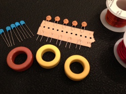 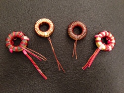
The
performance of these filters is obtained by employing the
three-resonator configuration,
using inductors wound on powdered-iron or phenolic torroidal cores, and
series-parallel connected, high-voltage, low loss NP0 ceramic
capacitors. If you're a contester, especially one who's involved in
multi-transmitter activities such as Field Day, these filters are what
you need!
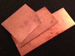
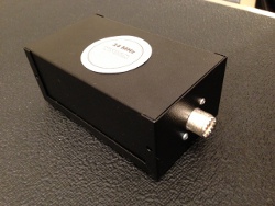
The materials you'll need to get started
are enclosures (we recommend
ones sized 5 1/4" X 3" X 2"), torroidal cores (T-130-17, T-130-6,
T-130-0, T106-0), copper-clad laminated sheets, ceramic disc capacitors
(15pF/4KV 10%, 110pF/2KV 10%, 30pF/3KV 10%, 220pF/1KV 5%), 18g, 16g,
and 15g magnet wire (for winding) and PL259
chassis connectors. For a complete list, as well as detailed
instructions, please refer to the following articles:
Clean Up Your Signals With Band Pass Filters
Clean Up Your Signals With Band Pass Filters
(Part 2)
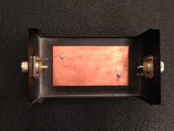 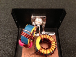
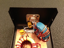
(Assembly process shown) - Note that the
copper-clad sheet is riveted
to the floor of the enclosure, and PL-259 connectors are mounted.
Next, a piece of braid or wire is used to ground the chassis
connector to the copper sheet, then the wound torroid is soldered,
along with appropriate capacitors, to create a 50W tap. The core bodies
are attached to the copper sheet with hot glue to prevent
wire-to-ground contact.
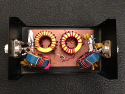
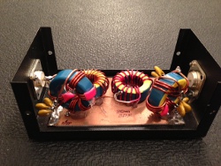
Our
filters were modified, assembled, and tuned by Roger Pience, N1XP.
Note, that since we use a slightly larger enclosure than the one
recommended in the original QST article, the torroidal cores can be
arranged in an orderly fashion with less chance of passband loss caused
by the proximity of the other cores or the enclosure.
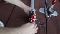
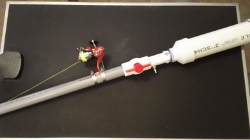
Building
a Pneumatic Antenna
Launcher
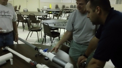
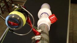
In
the Summer of 2012, WSSM members built pneumatic antenna launchers,
under the direction of Steve Freeman K1MV, who built the original
prototype. The launchers are constructed using 3" and 1-1/2" pvc
piping, and air gage, schrader valve, and a fishing reel. With about 40
pounds of air, they are capable of launching a weighted plastic slug
several hundred feet - perfect for putting up that next wire antenna!
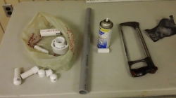
Parts List
- 3" PVC
pipe X 13" long
- 3" PVC
pipe dome cap
- Step
flange (3" down to 1 1/2" pipe)
- Total
of 24" long X 1 1/2" rigid non-metal conduit
- valve
for 1 1/2" pipe
- Fishing
reel
- 2 hose
clamps
- 1
Schrader valve
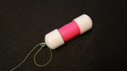
- 6" of
3/4" PVC pipe (to be cut in half for slugs)
- 4
3/4" dome caps (for slugs)
- Eyelet
(for attaching fishing line to slug)
- Fly
line
Tools
required
- Hacksaw
- PVC
cement
- Tape
measure
- Black
indelible marker
- Metal
file
- Electric
drill
- Flat
blade screw driver or 5/16 inch nut driver (to tighten hose clamps)
Begin
by cutting your pipe to the sizes shown below, then file
rough
edges and prefit. The open/close valve should be located about 4 - 1/2"
from the air chamber. Be sure to prep the areas to be glued, and allow
adequate drying time before applying any air pressure. I mounted the
shrader valve in the small pipe section, between the open/close valve
and the flange, and the pressure gage (optional) was mounted on the air
chamber section itself. Its a good idea to add a pressure gage, unless
you have an accurate one on your compressor or air tank, because this
is what determines distance when firing the slug. It is not necessary
or recommended that you fill it with any more than 40 pounds.

Mounting
the fishing reel is relatively simple. Any open reel will do, and its
personal preference whether to mount it on the top or bottom of the
pipe. As far as the slug goes, its just 3/4" PVC pipe, cut to about 6"
long and capped on both ends. Before assembling it, cut a small piece
of scrap wood for the inside for the eyelet to screw onto, and its a
good idea to fill the slug with sand so that it has enough weigh to
drop down the other side of that tree you'll be firing at. Another good
practice is to either paint it a bright or flourescent color, or wrap
it in a bright tape to make it easier to locate.
Firing
the antenna launcher is pretty easy, but it takes a steady hand. Once
air is pumped into the chamber, be sure not to point it at yourself or
anyone else as the projectile comes out very quickly. Its also a good
idea to wear safety glasses. The idea is to point it just slightly
above the tree that you're aiming at and quickly open the valve, to
release all the air in the chamber at once.
Building
a 3-element Tape Measure
Yagi
In
the September / October 2011 newsletter we discussed how to construct a
transmitter that can be used for radio direction-finding. But
there is another piece of equipment you'll need to consider before
heading out to the field for a transmitter hunt - an antenna! For
reasons of simplicity, and because they are relatively inexpensive to
make, we chose to build a "tape measure" antenna. Below, you'll find
directions on how to build your own 2 meter direction-finding antenna.
Parts List
- 3
feet of ½ inch schedule 40 PVC pipe
- 2-½
inch schedule 40 cross connectors
- 1-½
inch schedule 40 T-connector
- 1-½
inch schedule 50 caps
- 1
inexpensive tape measure (a 1 inch wide tape is recommended)
- 4
feet of coax cable with a connector on one end (UHF, BNC, SMA, etc.)
and the other end prepared for soldering
- 6
#12 (11/16 inch to 1 1/4 inch) hose clamps
- 5
inch piece of solid wire for hairpin tuning component (12 to
18 gauge will work)
Tools
required
- Hacksaw
or PVC pipe cutter
- Soldering
iron or gun
- PVC
cement
- Electronic
solder
- Wire
cutter
- Hot
glue gun
- Tape
measure
- Tin
snips
- Black
indelible marker
- Metal
file
- Flat
blade screw driver or 5/16 inch nut driver (to tighten hose clamps)
Step
1
Cut
an 11 ½ inch, and two 7 inch pieces of PVC pipe. Before cutting the
pipe, measure and mark the length using a black indelible
marker.
Step
2
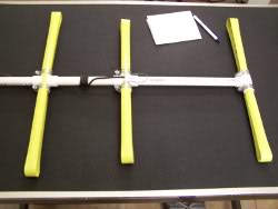
Assemble
the cut lengths of pipe as seen in the drawings to create the boom of
the antenna. Begin by connecting a T-connector to
one end of your 11
1/2 inch pipe, and a cross connector to the other. Then add one of the
7 inch pipes to the cross connector. Glue the remaining cross connector
to the end of this pipe and connect the last pipe to this cross
connector. Make sure that you align the cross connectors. The easiest
way to do this is to place them on a flat surface and twist them to be
flat with the surface. Finish this step by adding the cap to the open
end of the last pipe.
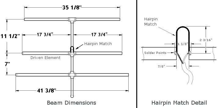
Step 3
Cut four pieces
from the inexpensive tape measure: 41 3/8 inch, 35 1/8 inch, and two
lengths of 17 3/4 inches. Be careful not to cut yourself on the sharp
corners or ends. Use your tin snips to carefully round off the sharp
edges.
Step 4
Now
attach the longest (41 3/8 inch)
piece of tape to the cross connector closest to the end with the cap.
It will be helpful to mark the center point (20 11/16 inches) with your
black indelible marker. Position the tape over the cross connector, so
the curve
of the tape is similar to the curve on the cross connector. Center and
secure the element with hose clamps on each side. Next,
attach the next longer element (35 1/8 inch) to the T-connector at the
opposite end of the boom in a similar fashion.
Step
5
The
next step is to take the 5 inch piece of wire and bend it into a "U"
shape about 3/4 inch wide. Then tin the ends of the wire. This will be
used to make the “hairpin match.” Scrape or file about 1/4 inch of
paint
off the back side of one of the ends of the two remaining pieces of
tape. Tin the bare areas, then attach the hairpin match and coax wire
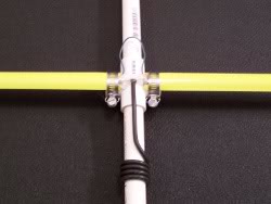
with solder as shown in the diagram.
Step 6
Next
attach this assembly to the boom using the two remaining hose clamps.
The soldered joints are then covered with hot glue to seal and help
waterproof it. For a balun, 4 or 5 turns of the coax feed
wound round
the boom should do the trick. Now your antenna is ready for use.
For more information on tape
measure yagis, check out the following
links:
Building
a Direction-Finding
Transmitter
One of the most enjoyable projects that we
tackled this summer was
constructing a pair of transmitters for radio direction-finding. Of the
two that we
built, one is a modulated-CW beacon, like the ones used for
International ARDF competitions, and the other is a "voice" beacon.
While researching for this project, we discovered Bob Simmons' (WB6EYV)
boards that could be used in their construction. We chose the MicroHunt
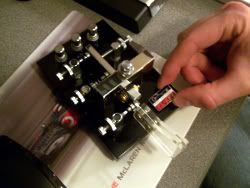
and SqwakBox transmitters.
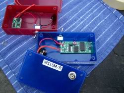
The
MicroHunt transmitter produces about 50 milliwatts of FM-modulated CW
on 2-meters on a board measuring 0.9 X 1.2 inches. It comes partially
assembled, and the PIC micro (that generates the CW message an ID at
regular crystal-controlled intervals) can be pre-programmed before
shipping. What we find upon delivery is a tiny board with mounting
points for power and an antenna.
The
MicroHunt is intended for competitive transmitter hunts, where multiple
transmitters operate sequentially on a single channel. For this reason,
crystal timing is essential to prevent transmission overlaps. It can
also be used as a DF "homing beacon" on free-flight balloons. It uses a
PIC 12F675 micro for supervision as well as a strap programmable,
crystal-controlled PLL synthesizer chip. Ground range, depending on
antenna, is typically well over a mile.
Its sister, the
SqwakBox, also produces 50 milliwatts of FM-modulated RF on 2-meters,
but its assembled on a slightly larger board, measuring 0.9 X 2.4
inches, and includes a voice record/playback chip with 60-second
recording capacity, and an integrated electret microphone to record a
message.
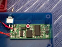
The
SqwakBox makes use of a PIC 16F84 micro for supervision, ISD2560 for
voice record/playback and an ICS525 PLL CPU clock generator chip.
Messages can be recorded by pressing a "record" button and speaking
into the integrated microphone. Its mostly intended for recreational
2-meter transmitter hunts.
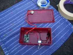
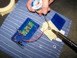
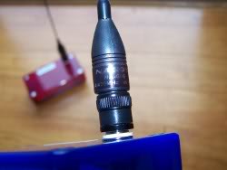
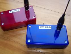
The first step regarding assembling
these transmitters is to find an enclosure. Just about any electronics
enclosure would work. We wanted something that was small, lightweight,
and had a good surface to mount an antenna, and on/off switch. Checking
several options online, we decided on plastic enclosures with removable
tops, and room enough to mount the necessary 9-volt battery. Believe it
or not, it was less expensive to purchase these from their manufacturer
in Poland and ship them, than from the US distributor. The antennas we
chose are Nagano 2 meter HT "flexi" ducks. We added an on/off switch so
we didn't have to worry about disconnecting the battery when not in
use. Besides the enclosure and switch, the only other parts required to
assemble them were BNC chassis connectors for the antenna, some wire,
and 9-volt battery connectors.
For more info on the parts used in
this project, please visit:
Doppler DF Instruments
Electronics Enclosures
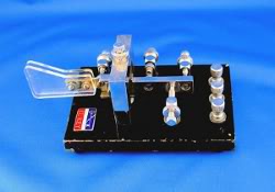
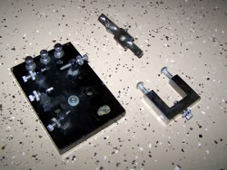
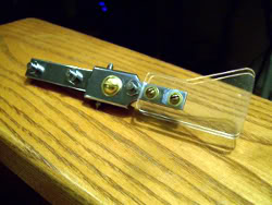
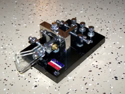
Restoring
the EL-Key
The
EL-Key is an important paddle in the history of amateur radio.
This single lever design was the first commercially manufactured paddle
offered to ham radio operators. They were made by R.E. Poucel (W2AYJ)
and Sid Shore (K2FC) doing business as "Poucel Electronics," a division
of Shore Mfg. Co., of Long Island NY, starting in 1959. Today they are
very scarce, and sought after by collectors.
While
searching for an EL-Key, we were looking for two important qualities -
a key which had all the components intact, and one which still had the
all-important name plate attached and undamaged. Everything else could
be restored.
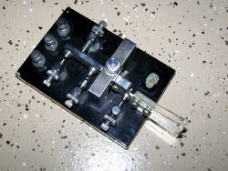
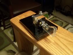
The
first step in any restoration process is to
decide what needs to be done. This one was in obvious need of new paint
on the base, and the lever, upon initial inspection, didn't function as
it should have - It was frozen and had no springing action. To begin,
we
would need to remove all of the components from the base. Before
disassmbling anything, however, its a good idea to take pictures and to
draw diagrams of how everything is attached and wired.
The
main carriage comes off with just two bolts, allowing removal of the
swing arm assembly. A flat head screw driver is the only tool that is
required. The rest of the components are simple upright posts which act
as electrical contacts, spring holders, or stops. They all remove with
a single machine screw, threaded from the underside of the base.
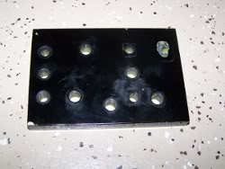
Once
everything is removed, the base can be sanded and prepped for paint. We
used two different grits of sandpaper with a sanding block. The first
was 220, followed by 320, making sure to smooth out all the chips and
scratches. Then the base was cleaned with solvent and set aside for
painting. Our base was painted by our good friends at Moody's Collision
Center, in Scarborough, Maine. We chose Volvo paint code 019, which is
a solid black, closely resembling the original color.
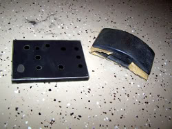
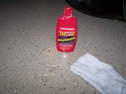
The
rest
of the components were cleaned and polished, and much of the stripped
or worn hardware was disgarded and replaced. For the plastic paddles,
which were yellowed and scratched, we used Mothers Plastic Polish,
which removed almost all of the surface scratches and yellowing. Then
we
gave it a finishing coat of Zymol Concours Glaze. The metal components
were polished with mag and aluminum polish, then finished with Zymol.
We discovered that the problem with the side-to-side motion of the
lever assembly was a missing spring, and a badly bent center bolt.
With these replaced, the left side motion was restored.
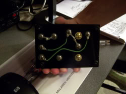
With
all the components repaired and polished, and the base back from the
body shop, we began the reassembly process. Consulting our photographs
and wiring diagram, the process went smoothly. The wiring was straight
forward, but required a few connectors to be soldered to the wires, and
to each other, to match the original layout. On removal, some of these
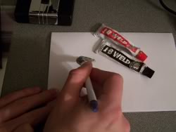
just fell apart. The finishing touch was to reapply the EL-Key
nameplate, which was done with a two-part epoxy called J-B Weld.
So
there you have it - a fully restored 1959 EL-Key, ready to get back on
the air and make some QSO's!
Constructing
a 20 meter Dipole
What
is a Dipole Antenna?
We
chose to build dipole antennas for our field activity because they are
cheap to produce, very efficient, and easy to construct. But why are
they effective? Let’s take a closer look, as we examine just what a
dipole is...
A
dipole
is a balanced antenna. It consists of
two haves, which extend in opposite directions from a feed point at the
center. It is commonly called a “half-wave dipole” since the entire
antenna is ½- wavelength long at the desired operating frequency.
Why
do we start here? In its simplest form the dipole is very dependable.
It’s easy to construct, tune, and to install, but it is also the
building block for other, more complex antennas. Once you understand
the techniques involved in making the dipole, they can be applied to
any type of wire antenna including the “Full Sloper,” “Inverted V,”
“End-Fed Zepp,” “Folded,” and “Trap” varieties of the dipole.
For
our example, we will construct a simple, center-fed dipole for the
20 meter band. To do this we need the following materials:
1 spool of 14 gage copper-strand wire (for the radiated elements)
1 spool of lamp cord, or “zip line” (for the center feed line)
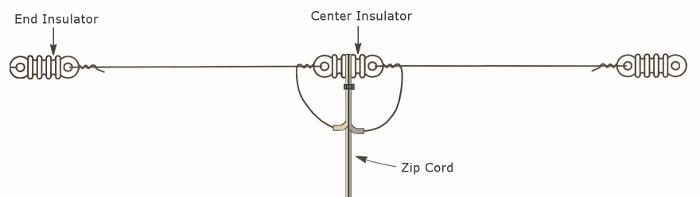
2 commercially available plastic end insulators
1 Center insulator
Nylon Rope |
The
following tools are also required:
Scissors
Wire Cutters
Soldering iron
Wire Strippers
Electrical Tape
Zip tie |
The
first step is to determine the total length of the antenna. We do this
(for frequencies up to 30 MHz), by using the following formula:
Length
of half-wave antenna in feet
= 492 X 0.95
/ f(MHz) =
468 / f(MHz)
A
half-wave antenna for 14.200 MHz
= 468 / 14.200 = 32.96 ft.
Divide this number
by 2 to get the length of each leg, and we have 16.48 ft. Keep in mind
that it’s a good idea to cut the wire a few inches longer than the
calculated length, since some of the resonating area of the wire will
be lost when it is tied back onto the insulators.
After
this
is done, cut a length of feed line. We used what is commonly called
“zip cord,” which is simply the electrical cord used on lamps or other
appliances. Cut a length of about twenty-five feet, and strip the ends
(about three inches on the end that will connect to the center
insulator). Although there are many ways to connect the feed line, we
chose to use a commercially available insulator made of plastic. This
could also be made from PVC tubing, wood, or even a scrap of Lexan. The
commercially made insulator has a fat round center with grooves in it,
and holes drilled on the ends. Secure the feed line to it by
wrapping it tightly around the center grooves and securing it with a
plastic tie, leaving enough of the stripped wire to loop around and
eventually connect to each leg.
Similarly,
attach the antenna legs to the center insulator, by looping each end
through the holes, and wrapping it around itself several times. Then,
connect one side of the stripped feed line to a leg of the
stranded antenna wire, and repeat with the other side. Do a good job of
soldering the antenna and feed line connections. When you’re finished
soldering, and it cools, wrap the connections with electrical tape for
water-proofing.
After
this
is completed, attach the end
insulators in a similar fashion, looping each end through a hole on the
insulator, but don’t solder just yet.
The
antenna is nearly
complete. Raise it to a working height, and check the SWR at several
frequencies across the band. Most dipoles require a little pruning to
raise the resonance the desired frequency. Remember to trim each end
equally. When you’re satisfied with the SWR, lower the antenna and
secure each end with solder, and when it cools, tape the connections to
waterproof.
There’s
a
few things to consider about how to
connect the feed line to your radio. We simply soldered a PL 259
connector to the zip cord and plugged it in directly to the radio, but
it’s probably a good idea to use a balun if the dipole is fed with
coax. The disadvantages of coax are increased RF loss and low working
voltage, but sometimes it can’t be helped. The most efficient way to
feed a dipole is with 450 ohm ladder line. Ladder line has extremely
low loss, and although zip cord has a little more, they both can stand
very high voltages (SWR).
Now
you’ve
done it. You made a dipole. Go tell the world!
One
advantage of the dipole is that its takes up little space, when
compared to a yagi, and doesn’t require a tower to get it up.
Simply put it in a tree, or if none is available, set up a mast or two,
and you’re on the air. They can be made of almost any wire or tubing,
and can be set up in an infinite number of configurations. The dipole
is popular because of its simplicity, and the fact that it can be
erected quickly in emergency situations. They are the choice of EmComm
operators and dx’ers alike. During our field operation on September
18th, we put up three dipoles for the 20, 40, and 80 meter bands in
just 15 minutes, and made nearly fifty contacts in just a few hours.
|