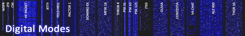
To many, amateur radio is just
about two things - either picking up a
microphone, or tapping a CW key to communicate with a fellow ham. But
there's another rapidly growing segment of the amateur radio community
to discover - the world of digital communications.
Prior
to about 1982,
there was really only one mode of choice, and it involved using a noisy
machine called a teletype, but since then radio amateurs have found a
use for that other piece of equipment in the shack - the
personal
computer.
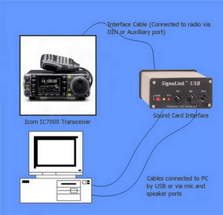
Software applications designed to use a PC's sound card have made
digital communications easier than ever.
Whether you're interested in "chatting" with another ham, want to send
and receive email, or transfer information, there's a mode that fits
your needs.
This
section is designed as an introduction to
some of the more popular digital modes. To learn more about a specific
one, click on the suggested links below each topic. For further info
about digital modes in general, and where to find them on the bands,
click on the links below:
Morse code, the grandfather of
all digital modes, is discussed in length on our CW
Page,
so we won't go into detail about it here, with the exception that CW is
in fact a digital mode consisting of elements having unequal lengths,
(dots and dashes). High Speed CW (HSCW) is a favorite of
hams who operate meteor scatter. By "high speed," we mean speeds that
are over 200 words per minute - That's way faster than anyone can copy
by ear! The
old fashioned way to operate meteor scatter would be to
record the bursts on a tape recorder, and then play it back at a much
slower speed, in conjunction with high speed memory keyers for
transmitting. Today this process is simplified by the use of computers,
but many still use tape or digital recorders.
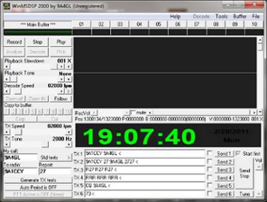
WinMSDSP
Software for HSCW
If you're curious about how
HSCW actually works, here's an excellent recording
by Jim McMasters (KM5PO), who explains in detail how hams slow down a
one-tenth of a second burst to make the CW clear and readable, using
the popular MSDSP software. Click
here
to download the latest version of MSDSP (for Windows 2000 or newer).
Radioteletype
(RTTY)
Although
Radioteletype, better known as RTTY, is the oldest method of
sending
keyboard-to-keyboard messages, it remains one of the most popular
digital modes. There's no question that new, error-correcting, and
bandwidth-efficient modes have captured their share of interest, but
RTTY remains the mode of choice for digital contesting and
DX'ing.
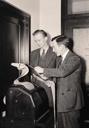
The
origins of the teletype can be traced to its predecessor, the stock
ticker, as far back as the 1870's, and eventually to the teletypewriter
(or teleprinter), which emerged around the turn of the twentieth
century. The first teleprinter as we know it, was invented by Charles
Krum, though it evolved through a series of inventions by a number of
other engineers, including Emile Baudot, Frederick G. Creed, Royal Earl
House, David Hughes, and Edward Kleinschmidt. Before that time, all
telegraph communications had used Morse Code. This, however, required a
qualified Morse operator at each end of the circuit, and the data rate
was limited to the copying and sending abilities of the individual
operators. Teletype offered several commercial advantages over Morse
Code - the most important being automatic copy.
The
standard coding system for teleprinters was originally the
5-unit
Baudot code, (named after its inventor, Emile Baudot). As explained by
the Wireless Institute of Australia, "When a key was
pressed, the teletype machine would generate a series of pulses by
switching a DC voltage on or off. The "on" state was referred to as the
"mark" state, and the off condition was called the "space" state"
(WIA). The
first pulse in the Baudot code was a "start" bit, then five
data
bits, followed by a "stop" bit, which marked the end of each character.
When these pulses reached the receiving machine, they would determine
which character was printed. The 5-bit code was later modified by
Donald Murray, and the resulting "Murray Code," became the standard
code used on commercial teletypes until it was superseded by the ASCII
code, which remains the standard today.
Shortly
after World War II, amateur radio operators in the U.S. started to get
their hands on obsolete but usable Teletype equipment from commercial
operators.
The first
two-way radio teletype QSO of record took place in
May 1946 between John Evans Williams (W2BFD) of Woodside, Long Island,
NY and Dave Winters, (W2AUF) of Brooklyn, NY. These early radio
teletype operators used audio frequency shift keying (AFSK), usually on
2 meters, since FSK modulation was not yet authorized by the FCC.
Operation
on the HF bands was initially accomplished using “make and break”
keying, with the first transcontinental two-way RTTY QSO taking place
on 11 meters between W1AW in Newington, CT, and W6PSW in California.
While QSO’s could be made using this method, it was quickly realized
that FSK was superior. In 1953, after being petitioned by the likes of
Merrill Swan (W6AEE) of the RTTY Society of Southern California, and CQ
Magazine editor Wayne Green (W2NSD), the FCC investigated and amended
part 12 of the Regulations to allow for FSK to be used on the HF bands.
Teletype over radio relies
on FSK, or Frequency Shift
Keying of the RF carrier. As mentioned earlier, the teletype machine
responds to on-off DC pulses. Over the air, its customary to move the
carrier to a different frequency for the "space" signals and back again
for the "mark" signals. Carrier shifts of 850 Hz plus or minus 50 Hz
was initially specified for amateur radio use by the FCC. Use of this
wide shift, however, proved to be troublesome to amateur operators.
Commercial operators had already discovered that 100 Hz shifts,
commonly called "narrow" shift, worked best on the HF bands, and after
a petition to the FCC, Part 12 was amended in 1956 to allow hams to use
any shift that was less than 900 Hz (Beishel).
RTTY
is a very simple technique that uses a 5-bit code to represent all the
letters of the alphabet, the numbers, some punctuation, and control
characters. At 45 baud, typically, each bit is 1/45.45 seconds long, or
22 ms, and corresponds to a typing speed of 60 words per minute.
Although other speeds for sending are allowed, 45 baud has become the
most popular for amateur radio. One downside of RTTY, however, is that
there is
no error correction.
On
March 17, 1980, the use of ASCII was
approved for use by amateur radio stations, with speeds up to 300 baud
(from 3.5 - 21.25 MHz), and 1200 baud (from 28 - 225 MHz). Speeds of
19.2 kilobaud is authorized on frequencies above 420 MHz.
Operating
RTTY on FLDIGI
Since the
1980's, teleprinters and Frequency Shift
Converters, (which are used to make RTTY function on single side band
radios), have been replaced by PC's. Software programs have been
written to decode and transmit RTTY messages, and have made the mode
accessible to many more operators. Two popular softwares that can
decode and send RTTY, using the sound card of your PC, are FLDIGI
and MMTTY.
For more
information about
Radioteletype, click on the links below:
Where
can I find RTTY Signals?
RTTY
signals can be found on all the HF bands, in the "digital mode"
segments. A number of different modes are used in these segments, but
they can usually be determined by ear. RTTY signals are characterized
by a regular shifting back and forth between two tone frequencies.
You're most likely to find RTTY activity around these frequencies:
160 METERS 1.800 to 1.810
80 METERS 3.560 (calling) to 3.590
40 METERS 7.080 to 7.100
30 METERS 10.130 to 10.140 20
METERS 14.070 to 14.095
17 METERS 18.100 to 18.105 15
METERS 21.070 to 21.100
12 METERS 24.920 to 24.925
10 METERS 28.070 to 28.150
6 METERS 50.100 to 50.300
Amateur
Teleprinting Over Radio (AMTOR)
AMTOR
was derived from the commercial SITOR
(Simplex Telex Over Radio)
system, developed for maritime use in the 1970's. Like its predecessor,
RTTY, AMTOR uses a variation of
the Baudot Code. It also relies on FSK modulation, but unlike RTTY, it
offers a form of error correction. When two AMTOR stations are
connected
they employ an error detection method called Automatic Repeat Request,
(ARQ) - referred to as AMTOR mode A. With this method, three characters
are sent at a time, and the receiving station determines if the
mark/space ratio is correct. If the received code doesn't match a 4:3
ratio, the receiver assumes an error has occured, and requests that the
original data be resent. When AMTOR messages are sent to a group of
stations, Forward Error Correction (FEC) - refered to as AMTOR mode B,
is the method used. In FEC mode, the transmitting station sends each
character twice, and the receiving station checks each one
for the correct mark/space ratio. With a set operating rate of 100
baud, and a frequency shift of 170 Hz, AMTOR does not effectively
contend with the speed and error correction of the more modern ARQ
modes like PACTOR, but it is known for its reliability and performs
well even in poor and noisy HF conditions.
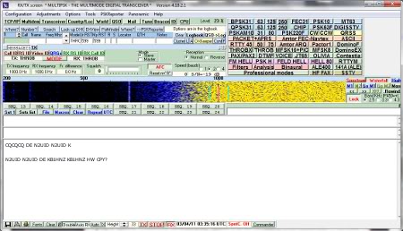
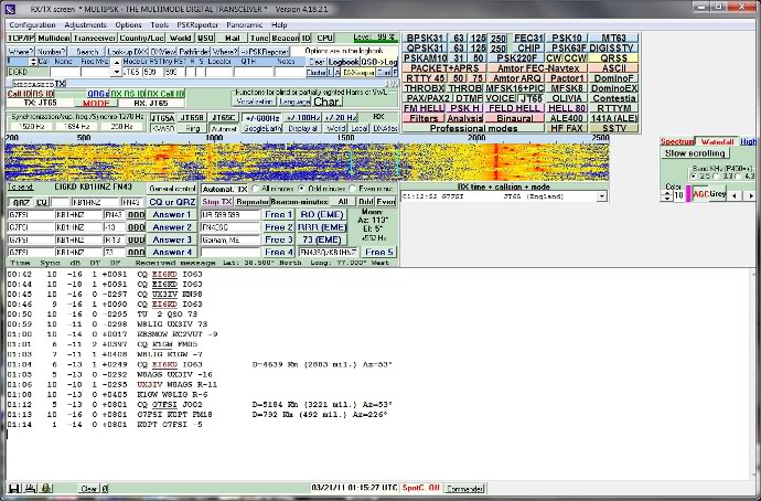
AMTOR QSO using Multipsk software
AMTOR
enjoyed widespread popularity from about 1983 through 1991,
and is
known for its distinctive sound, which is like a rapid series of
chirps. According
to Steve Ford (WB8IMY), hams made "ample use of its error-free text
capability, even setting up automatic AMTOR mailbox operations (MBO's),
where messages could be stored for later retrieval from anywhere in the
world" (Ford).The
mode was
originally designed to be used with a Terminal Node Controller
(TNC) and it can still be found on most multi mode
processors.
Though not available in a wide variety
of
softwares,
many amateurs make
use of programs that utilize a PC sound card. One of the most popular
software programs for
operating AMTOR (ARQ) is Multipsk,
which is freeware, and a good program to receive AMTOR in FEC mode is TrueTTY,
developed by DXSoft.
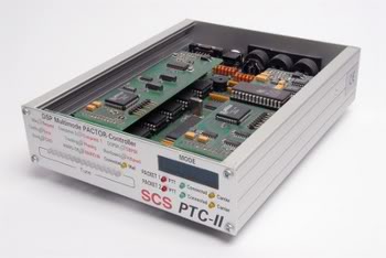
PACTOR
PACTOR
is an FSK mode which was developed in Germany by Ulrich Strate (DF4KV),
and Hans-Peter Helfert (DL6MAA) for Special Communications Systems GmbH
(SCS), and released to the public in 1991. Like its name suggests,
PACTOR is an evolution of both AMTOR and Packet Radio, and began as
early as 1986 as experiments with AMTOR protocols in an effort to
improve performance in noisy HF conditions.
PACTOR offers enhanced error correction and a considerably higher
200 baud transfer rate. It is primarily used today for sending and
receiving email over the radio.
When
choosing a digital mode to use, its a good idea to weigh the strengths
and
weaknesses of each type, but also its cost. PACTOR I is an open
technology and modems are
relatively inexpensive, which has helped it catch on. But the two
enhanced modes, PACTOR II and PACTOR III, (both of which are PSK
modes), offer much faster data
transfer, and have been kept proprietary by the company that developed
them. As a result, SCS is the only
source for modems capable of
operating PACTOR II and III, and the prices of some of these modems -
which can be as much $1200.00 - discourage many potential users.
The best resource for information about PACTOR is the SCS
website.
Golay Teleprinting Over Radio
(GTOR)
G-TOR
is a protocol that is nearly three times faster than PACTOR, and
incorporates features like Golay forward error correction, full-frame
interleaving, on-the-fly Huffman data compression (with run-length
encoding), fuzzy acknowledgments (for error tolerance), a long ARQ
cycle of 2.4 seconds, and a link-quality based transmission rate. All
of these combine to minimize the effects of atmospheric noise while
resulting in a mode that is robust and compatible with
existing equipment.
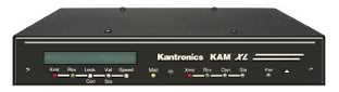
Kantronics
KAM XL
G-TOR
uses frequency-shift-keying like PACTOR and Packet radio, but its
transmission rate can change depending on band conditions.
While
attempting to peform all transmissions at 300 baud, it drops to 200
baud if difficulties are encountered, and to 100 baud if necessary. Frames
are sent in normal ASCII or are
Huffman and run-length encoded,
depending upon which is more efficient on a frame-by-frame basis. The
Huffman table for G-TOR is unique, in that unlike PACTOR, it
emphasizes English over German character usage and upper and lower case
characters are swapped automatically (frame-by-frame) in a third
attempt to compress data. G-TOR transmits either 24, 48, or 72
characters depending on baud rate. Errors are detected at the receiver
using a CRC-16
checksum, and depending on how much is missed, it will
request a repeat of the last data or parity, or a change in baud rate
(Anderson).
G-TOR
is a proprietay mode developed by Kantronics, Inc. It
was based somewhat on concepts outlined in the MIL-STD-188-100 series
of documents, and a protocol devised by M.Golay, that was used by the
Voyager space craft to send pictures of Saturn and Jupiter
back to Earth.
Although it was designed to make use of existing multi-mode TNC
hardware, the fact that it is only available from one manufacturer has
kept it from gaining widespread popularity. Despite this, however,
G-TOR is gaining ground and respect in the world of HF data
communications.
The best resource for information about G-TOR is the Kantronics
website.
HF Packet
HF
Packet is an FSK mode that uses the standard AX.25 protocol -
the
same one used for VHF Packet Radio. HF Packet, however, uses a
300 baud
rate compared to the 1200 baud used on VHF. Although the HF
version of packet radio uses a much reduced bandwidth, it still has the
ability to "node" many stations on one frequency.
AX.25
- the communications protocol used for Packet radio - was
developed in the 1970's and is based on the wired network protocol
X.25.
Because of the difference in transmitting wirelessly by radio, and
because of different addressing schemes,
X.25 was modified to suit
amateur radio's needs. AX.25 also includes a "digipeater" field to
allow other stations to automatically repeat packets to extend the
range of transmitters. This practice usually takes place on VHF, where
range is limited to line-of-sight.
Packet
technology was first developed in the mid-1960', and by the end of the
decade was put into practical use in the ARPANET.
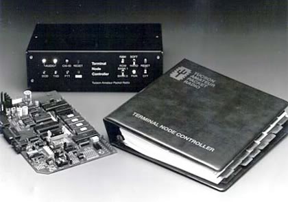
TAPR's
Terminal Node Controller, TNC-1
Initiated
in 1970,
the ALOHANET, based at the University of Hawaii, became the first
large-scale packet radio project. Amateur packet began in Montreal,
Canada, with the first transmission occurring on May 31st,
1978.
Packet
technology advanced further with the Vancouver Amateur Digital
Communication Group's (VADCG) development of a Terminal Node Controller
(TNC) in 1980. The current standard for TNC's came about in
1981 at
a meeting of the Tuscon Chapter of the IEEE Computer Society. Among the
topics discussed was the feasibility of developing a TNC that would be
available to amateurs at a modest cost. The Tuscon Amateur Packet
Corporation (TAPR) was formed as a result, and on June 26th, 1982, Den
Connors (KD2S), and Lyle Johnson, (WA7GXD), made the first packet
contact using a TAPR unit. These early prototypes eventually led to the
TNC-1, and finally to the TNC-2, (1984-1985), which is now the basis
for most packet operations worldwide.
Packet
radio has seen a wide variety of uses, ranging from the Packet Bulletin
Board System (BBS), which offers the ability to send and receive
personal messages, or send and receive messages and bulletins intended
for people around the world. Since BBS is part of a national system of
other BBSs, it has the ability to pass information to any other BBS in
the US or the world.
Other uses include DX Packet Clusters, where
amateurs connect to their local cluster to receive reports on the
latest DX spotted on the bands. Packet has also been used for
transmitting messages via orbiting satelites, and the International
Space Station.
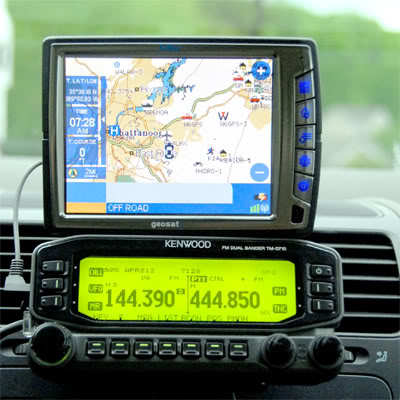
One
of the most popular uses of Packet Radio of late is the Advanced Packet
Reporting System, or APRS.
Invented by Bob Bruninga
(WA4APR), APRS is
an application that runs "on top of" AX.25. The application utilyzes
GPS data to plot a packet station's location on a map. Signals
utilizing this mode are found in the 40 and 30 meter bands on HF, as
well as on VHF and UHF.
Steve
Ford (WB8IMY), writes in a QST article, that "The problem with
Packet, as far as HF communication is concerned, is that it requires
strong quiet
signals at
both ends of the path to function efficiently. Packet doesn't tolerate
signal fading, noise or interference, which makes it a poor choice for
the chaotic world of HF" (Ford). Because of this, Packet is primarily
used
to pass routine traffic and data between areas where VHF repeaters may
be lacking. Still popular with TNC users, there are some software
programs available for use with PC sound cards. One of them is
the AGWPacket Engine, which came as part of the software suite for many
of the Rigblaster products. It can also be downloaded
here.
CLOVER
CLOVER
is a PSK mode, unveiled in 1993 by HAL Communications, which
provides a full duplex simulation. Steve Ford, WB8IMY, wrote in a QST
article that CLOVER "was one of the first HF digital modes to use
sophisticated data coding, coupled with complex modulation schemes and
digital processing technology, in an effort to overcome the vagaries of
HF." CLOVER has impressive performance even in the face of weak signals
and terrible band conditions. Its key characteristics are bandwidth
efficiency with high error-corrected data rates. CLOVER adapts to
conditions by constantly monitoring the received signal. Based on this
monitoring the program determines the best modulation scheme to use.
Upon
its release the initial price tag put CLOVER out of the reach of many
hams, dampening interest in the mode, but price reductions and the
introduction of CLOVER II has helped it retain a small, yet dedicated
following. In order to use CLOVER, you must have a HAL processor, a
computer, and a single sideband transceiver.
PSK-31
Peter
Martinez (G3PLX), who is responsible for adapting the commercial SITOR
mode as AMTOR for the amateur radio bands, is credited with inventing PSK31. Over
the last decade the
mode has been among the most popular of
all HF digital modes, especially for keyboard-to-keyboard operating,
but that almost wasn't the case. In 2001, Steve Ford,
author of the ARRL HF
Digital Handbook, wrote
that "for a few years, PSK31 languished in obscurity because special
DSP hardware was required to use it. But in 1999, Martinez designed a
version of PSK31 that needed nothing more than a common sound card"
(Ford). To make it even better, the software was made available for
free. Shortly thereafter, other programs like DigiPan and WinPSK, made
operating PSK31 easier than ever.
PSK31
combines the advantages of simple variable length text code with a
narrow bandwidth phase-shift-keying (PSK) signal using DSP techniques.
The standard BPSK mode offers unconnected live keyboard-to-keyboard
chat without Forward Error Correction, at a 31 baud rate. Most ASCII
characters are supported, with faster sending speeds when using lower
case letters. A second version having four (quad) phase shifts, called
QPSK is also available.
The chief advantage of using PSK31 is its
narrow bandwidth but this isn't achieved naturally. With digital phase
modulation, the phase changes abruptly, and without additional
measures, wide sidebands would be created.
M. Greenman,
offers a good
explaination of how this is counteracted, saying "To prevent this,
these modes also include 100% raised-cosine amplitude modulation (ASK)
at the symbol rate, which reduces the power to zero at the phase range.
Because of this, the signal bandwidth is relatively narrow"
(Greenman).
PSK31
is not
an error free digital mode, although improved versions such as the PSKR
varieties have been developed to improve on its lack of robustness
under adverse conditions. PSKR uses a similar design as the MFSK modes,
with a convolutional encoder and interleaver, however this comes at the
expense of data speed (which is sometimes divided in half when compared
to standard BPSK). The PSKR modes are designed for use with
data transfer applications
such as pskmail, flarq, or other automated-repeat-request
applications.
According
to Greenman, "the BPSK modes work well on a quiet, single-hop
path, but give poor performance in most other conditions"
(Greenman). BPSK31 is the default
calling mode, although PSK63F (which does use a form of Forward Error
Correction) is also well suited for keyboard-to-keyboard
chat. The slower QPSK modes seem most affected by ionospheric
doppler phase changes, although Differential PSK helps to maintain sync
and reduce the effects of doppler, by allowing the receiver to measure
phase difference from symbol to symbol.
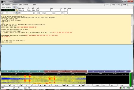
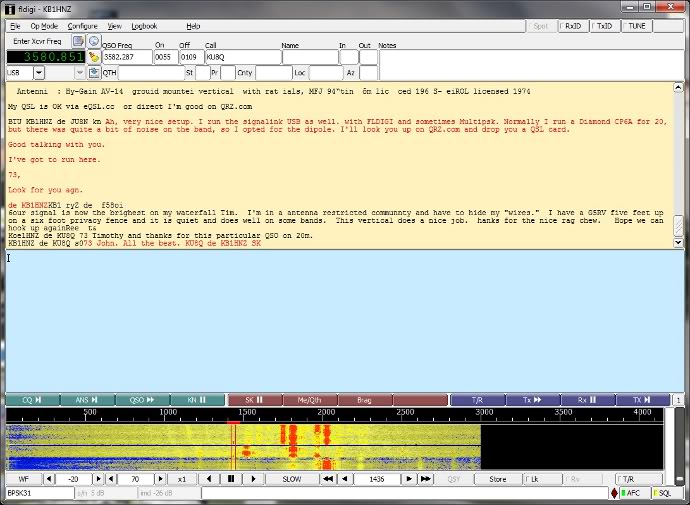
Operating BPSK31 using FLDIGI. Note, the
various red lines on the waterfall indicate other stations.
A
couple of
excellent software programs for PSK31 are FLDIGI
and DigiPan.
MT63
MT63
is a new DSP based, keyboard to keyboard, mode that utilizes Walsh 64
bit forward error correcting (FEC), with interleaf of each character
every 6.4 seconds. It is operationally similar to RTTY and PSK31,
however, the data components are spread over 64 tones, spaced 15.625 Hz
apart (1 kHz width), each bipolar phase shift keyed at 10 Hz. Because
the information is spread both in time and frequency, time domain
interference has little effect. MT63 was invented by a Polish radio
amateur, Pawel Jalocha, (SP9VRC), who sought to develop a reliable
replacement for RTTY.
The
wide bandwidth of MT63 makes it less
desirable on crowded ham bands
such as 20 or 80 meters, where the movement has been toward narrow
signals like PSK31. Also, the complex modulation scheme brought about
issues with getting FCC approval for amateur use.
MT63 has, however, become the mode of preference for MARS traffic nets.
In a Navy MARS report on the mode, it was concluded that operation was
"easy and inexpensive," and that MT63, "especially at 2000Hz, is much
faster than AMTOR or Packet FEC" (Navy MARS).
THROB
THROB
is yet another new DSP sound card mode, which uses a possible 9 tones
spaced 8 or 16 Hz apart, which gives a bandwidth of 72 or 144 Hz
respectively. According to Ernie Mills, (WM2U), the mode has "three
transmission speeds, 1, 2 and 4 throbs/sec which gives data rates of
10, 20 and 40 wpm respectively." THROB is an experimental mode written
by Lionel Sear, G3PPT, who is active in the development of many small
programs for amateur radio use, including a variation of Hellschrieber,
called Slowfeld. The THROB program, according to J. Duffy Beishel,
(WB8NUT), is "an attempt to push DSP into the area where other methods
fail because of sensitivity or propagation difficulties and at the same
time work at a reasonable speed" (Beishel).
Two
excellent soundcard programs that feature THROB are Multipsk
and FLDIGI,
as well as the program
Sear developed for the mode, called THROB 2000.
MFSK-16
One
of the newest amateur digital modes, MFSK
16, was developed by Nino
Porcino (IZ8BLY) of Italy. It is somewhat similar to THROB, but has 16
carriers,
spaced 15.625Hz
apart and operates at 15.626 baud. MFSK 16
occupies about 316 Hz bandwidth with a data rate of 62.5 bps, or about
80 wpm. Ernie Mills (WM2U) explains in an article about the mode, that
MFSK 16 has built-in FEC error correction "which reduces the text
throughput to about 42 wpm or 31.25 bps" (Mills). According to J. Duffy
Beischel (WB8NUT), the wide bandwidth allows for "greater
immunity to multi path phase shift,"
and improved Varicode
helps to increase the efficiency of sending extended ASCII characters,
"making it possible to transfer short data files between
stations
under fair to good conditions" (Beischel).
Multi-Frequency
Shift Keying can be traced back to the mid 1930's with
the development of a system called LMT. A variant called Coqulet came
about in the 1950's, as did Kineplex and Piccolo, the later of which,
according to Ernie Mills, (WM2U), was used by the British Foreign
office. DTMF, which is widely used today with touch tone telephones is
also a form of MFSK.
MFSK
16 is quickly becoming the standard for reliable keyboard to keyboard
communications, and is available in several popular programs, including
IZ8BLY's "Stream" software, FLDIGI, and Mutipsk.
Hellschreiber
Hellschreiber
is an early facsimile mode invented by Dr. Rudolf Hell in
1929. It is known to have been used by the Germans during World War II,
and some receivers were even built by British and American intelligence
to
intercept communications. The mode, however, seemed to be forgotten
about after the war, until it was rediscovered in 1979 by Hans Evers,
whose article "The Hellschreiber, A Rediscovery,"
was published in Ham Radio
magazine. In the article, Evers argues that Hellschreiber, although it
existed simultaneously with RTTY, was never fully accepted by the
amateur community probably because of the abundance of RTTY machines
that flooded the market at low prices after the war.
Unlike
the RTTY machine, in which received pulses determine the character to
be, the
Hellschreiber uses the transmitted pulses to directly
write images
of characters on
paper tape. Thus, according to Hans Evers (PA0CX), "Hellschreiber
writing could be considered a type of facsimile, covering seven images
per character, with seven elements per line." The Hellschreiber
of the World War II Wehrmacht type that Evers used is described
as being "somewhat slower than the RTTY machine," producing 2 1/2
characters per second. Nevertheless, he says, "a respectable 25 words
per minute is achieved."
Steve
Ford,
author of the ARRL HF
Digital Handbook, describes the Hellschreiber as being visual, "That is to
say, the signals paint
the text on your screen much in the same sense that a television or fax
signal paints an image" (Ford).
Feld-Hell,
a variation of Hellschreiber, works by keying a CW transmitter on for
every black portion in a text character, and off for every white space.
This method has captured the interest of QRP operators since it
requires only a simple CW transceiver to be used with sound
card
software on a PC. Another variation, called Multi-tone Hell, or
MT-HELL, creates text images by using different frequencies (or tones),
to represent the black and white areas.
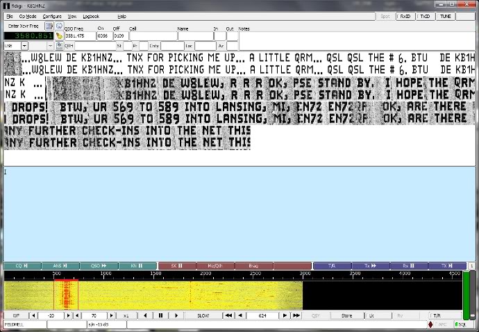
Operating Feld Hell using FLDIGI, during
the
Feld Hell Club net on 40 meters
Where
can I find Hell signals?(coutesy of
Feld-Hell club)
In
general, most Hell activity will take place on the frequencies listed
below. As with any ham radio mode, these are suggested frequencies, and
its always good practice to listen before transmitting:
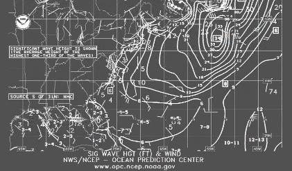
Although
not an amateur radio mode, many PC soundcard programs that hams use
have the ability to receive Weather Fax transmissions. HF Weather Fax
is a means of transmitting graphic weather maps and other images via
shortwave or HF radio. Maps or pictures are received using a dedicated
radio fax receiver (usually on commercial ships), but can also be
received using a single sideband receiver connected to an external
facsimile recorder or PC equipped with a soundcard interface and
application software.
The
main source for HF Weather Fax in the U.S. is the National Weather
Service, whose fax program prepares high seas weather maps for
broadcast via four U.S. Coast Guard (Boston, New Orleans, Pt. Reyes,
and
Kodiak) and one DOD transmitter site (Honolulu). These broadcasts
are prepared by the Marine Prediction Center, Tropical Prediction
Center, Honolulu Forecast Office and Anchorage Forecast Office. Limited
satellite imagery, sea surface temperature maps and text forecasts are
also available.
Wave height
prediction received
from station NMF in Boston
The
International Ice Patrol also broadcasts radio fax
charts from Boston sharing the same transmitters. Other stations, in
Halifax and Sydney, Nova Scotia can be received on the east coast of
the U.S. when band conditions are favorable.
All
National Weather Service broadcasts employ a radio fax signal of 120
lines-per-minute (LPM) and an Index-of-Cooperation of 576. These values
must be entered into either the fax printer or software program in
order for the image to be displayed properly.
OLIVIA
is a new digital MFSK mode created in 2005 by Pawel Jalocha (SP9VRC),
who also developed MT63. OLIVIA seems highly resistant to fading and
noise, and incorporates Forward Error Correction (FEC), based
on
Walsh functions. As with other modes, OLIVIA has several variants, each
having a different bandwidth (from 500Hz to 2 kHz) and different tones.
The mode can combine 4-256 tones (2n),
with a 250, 500, 1000, or 2000 Hz bandwidth. The prevailing standard
setting is 32 tones and 1000 Hz with 31.25 baud. This allows
for ±125 Hz of mis-tuning.
A new variation, CONTESTIA,
is a digital MFSK mode derived from OLVIA by Nick Fedoseev (UT2UZ). One
of the best programs that features both of these new modes is FLDIGI.
JT65
JT65
is a digital protocol intended for amateur radio communications with
extremely weak signals. The mode debuted as part of the WSJT software
suite developed by Nobel Prize winning scientist, Dr. Joe Taylor
(K1JT). Designed to optimize Earth-Moon-Earth contacts and meteor
scatter on VHF (or UHF), the mode has become popular
of late
on the HF bands as well. If you're tuning around the weak signal
portions of the bands, you may have already come across its strange
musical tones of varying pitch and wondered what it was.
Operating JT65A with Multipsk on 40
meters
JT65
uses precisely timed transmit-received sequences. You transmit for
about 1 minute and listen for one minute. Transmission actually begins
1 second after the start of a UTC minute and stops precisely 46.8
seconds later. There is a 1270.5 Hz synchronizing tone, and 64
additional
tones. Messages sent via JT65 are compact and efficient. They usually
include just the basic information required for a valid contact, such
as call signs, grid locators, and signal reports. EME
operators may just send "RO," which means "I've copied both calls and
my signal report, and your report is...", "RRR," which means
"the
QSO is complete," and "73," which means "best regards, end of
contact."
JT65
has three sub-modes known as JT65A, B and C. They are identical except
for the spacing between transmitted tone intervals. At the present
time, JT65A is generally used on HF and 6 meters, JT65B on 144 and 432
MHz, and JT65C on 1296 MHz.
JT9,
developed by Joe Taylor K1JT, is intended for MF and HF use, and was
introduced in an experimental version of the WSJT software, known as WSJT-X. It uses the same logical
encoding as JT65, but modulates to a
9-FSK signal. With 1-minute transmission intervals, JT9 occupies less
than 16 Hz bandwidth. JT9 also has versions designed for longer
transmission intervals of 2 minutes, 5 minutes, 10 minutes or 30
minutes. These extended versions take increasingly less bandwidth and
permit reception of even weaker signals.
FEC
in JT9 uses the same strong convolutional code as JT4: constraint
length K=32, rate r=1/2, and a zero tail, leading to an encoded message
length of (72+31) × 2 = 206 information-carrying bits. Modulation is
nine-tone frequency-shift keying, 9-FSK at 12000.0/6912 = 1.736 baud.
Eight tones are used for data, one for synchronization. Eight data
tones means that three data bits are conveyed by each transmitted
information symbol. Sixteen symbol intervals are devoted to
synchronization, so a transmission requires a total of 206 / 3 + 16 =
85 (rounded up) channel symbols.
The
sync symbols are those numbered 1, 2, 5, 10, 16, 23, 33, 35, 51, 52,
55, 60, 66, 73, 83, and 85 in the transmitted sequence. Tone spacing of
the 9-FSK modulation for JT9A is equal to the keying rate, 1.736 Hz.
The total occupied bandwidth is 9 × 1.736 = 15.6 Hz.
Modulation:
9-FSK
Bandwidth:
15.6 hz
TX
duration: 49 secs.
Baud:
1.736
Min
SNR:-27db based on 2500hz bandwidth noise
If
you ran across this on the radio and were not familiar with the mode
you might think it is a birdie in your radio due to the small bandwidth.
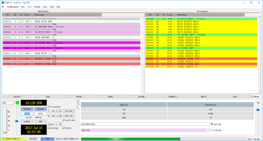
FT8
Joe
Taylor, K1JT, announced on June 29, 2017 the availability of a new mode
in the WSJT-X software, called FT8. FT8
stands for "Franke-Taylor
design, 8-FSK modulation" and was created by Joe Taylor, K1JT and Steve
Franke, K9AN. It is described as being designed for "multi-hop Es where
signals may be weak and fading, openings may be short, and you want
fast completion of reliable, confirmable QSO's".
According
to Taylor, the important characteristics of FT8 are:
T/R
sequence length: 15 secs.
Message
length: 75 bits + 12-bit CRC
FEC
code: LDPC (174,87)
Modulation:
8-FSK, keying rate = tone spacing = 5.86 Hz
Waveform:
Continuous phase, constant envelope
Occupied
bandwidth: 47 Hz
Synchronization:
three 7x7 Costas arrays (start, middle, end of TX)
Decoding
threshold: -20 dB (perhaps -24 dB with a priori decoding, TBD)
Operational
behavior: similar to HF usage of JT9, JT65
Multi-decoder:
finds and decodes all FT8 signals in passband
Auto-sequencing
after manual start of QSO
Compared
to the so called slow modes (JT9, JT65, QRA64), FT8 is a few dB less
sensitive but allows completion of QSOs four times faster. Bandwidth is
greater than JT9, but about 1/4 of JT65A and less than 1/2 QRA64.
Compared with the fast modes (JT9E-H), FT8 is significantly more
sensitive, has much smaller bandwidth, uses the vertical waterfall, and
offers multi-decoding over the full displayed passband. Features not
yet implemented include signal subtraction, two-pass decoding, and use
of a priori (already known) information as it accumulates during a
QSO."[14]
There
are new softwares available which include JT65, JT9, and FT8. Two of
the most popular
are WSJT and Multipsk. Both can be downloaded from the links below:
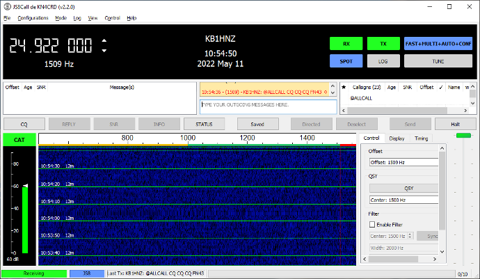
JS8Call combines the
robustness
of FT8 with a messaging and network protocol layer for weak signal
communication on HF, using a keyboard messaging style interface.
Although it is
a derivative of the WSJT-X application (described above), it has been
restructured
and redesigned for message passing using a custom FT8 modulation called
JS8.
According
to Jordan Sherer
KN4CRD, “JS8Call is not designed for any specific purpose other than
connecting
amateur radio operators who are operating under weak signal
conditions.” The
software is “heavily inspired by WSJT-X, Fldigi, and FSQCall and would
not
exist without the hard work and dedication of the many developers in
the
amateur radio community.”
JS8Call
is an open-source
derivative work licensed under and in accordance with the terms of the
GPLv3
license. The source code modifications are public and can be found in
the js8call
branch of this repository: https://bitbucket.org/widefido/js8call/
Slow
Scan Television is a method of transmitting medium and high resolution
images over the air using standard audio modulation. Most modern SSTV
activities are computer based, and are relatively easy to set up. All
that is required to join the fun is a radio, a sound card interface,
and a PC with SSTV software.
The
concept of Slow Scan Television dates back to 1957, when Copthorne
MacDonald began experimenting with an electrostatic monitor and a
vidicon tube. The FCC legalized SSTV for amateur radio use in 1968, but
because of the specialized equipment needed, few took it up. At the
time, operating the mode required a scanner or camera, a modem (to
create audio tones), and a cathode ray tube with long persistence
phosphors, (that would keep an image visible for ten seconds or
longer). Many SSTV operators used tubes found in surplus radar
equipment.
A
Slow Scan Television transmission consists of horizontal lines, scanned
left to right, with color components sent seperately one line after
another. The color encoding and order of transmission can vary between
modes. To create an image, an audio tone is frequency modulated and
transmitted (usually as a single sideband signal). The audio signal has
a frequency of 1200 Hz for a frame pulse, 1500 Hz for black, and up to
2300 Hz for peak white. Other signals, called synchronization pulses
are represented by a frequency lower than the one representing the
black level. These are said to be blacker than black, and therefore
cannot be seen on the screen.
In
the beginning, SSTV images were produced by an 8-second black and white
transmission format, but it didn't take long for experimenters to get
tired with black and white. Soon, they devised clever ways to send
color images using the same equipment. The frame - sequential method
involved sending the same picture three times, with a red, green, or
blue colored filter placed in front of the camera lens.
The
receiving station would take three long-exposure photographs of the
screen, also placing red, green and blue filters in front of the film
camera's lens at the correct time. John Langner (WB2OSZ) writes in the
ARRL Handbook, that this method, "had some drawbacks, as any noise on
the band could ruin the image registration (overlay of the frames), and
spoil the picture."
Images
could then be saved and simultaneously displayed on an ordinary color
TV. (Langner). The Line-Sequential method remedied this by
scanning each line three times, allowing pictures to be received in
full color in real time. Early line-sequential modes, such as Wrasse
SC-1, used a horizontal sync pulse for each of the color components,
but a drawback to this method, according to Langner, "is that if the
receiving end gets out of step, it won't know which scan represents
which color" (Langner). Robot Research, in an attempt to solve these
issues, moved away from the traditional RGB color model with their
1200C modes, using Luminance and Chrominance signals instead. With this
method, the first part of each line contains the luminance information,
(which is a weighted average of the R, G and B components). The
remainder of each line contains the chrominance signals, (which is used
to convey the color information of the picture). 1200C is efficient,
allowing a 120 line image to be sent in about 12 seconds compared to
the usual 24, but picture quality suffers, especially on images with
sharp, high-contrast edges. One of the most important advantages of
1200C is its compatibility with older black and white equipment
(Langner).
The
Martin (M1) and Scottie (S1) modes, which are two of the most popular
today, have returned to RGB encoding. Both use a single horizontal sync
pulse for each set of RGB scans, and differ only in the timing.
Another
innovation, introduced by Robot Research, is
Vertical-Interval-Signalling, which is a way of encoding the
transmission mode into the vertical sync signal. VIS is composed of a
start bit, 7 data bits, an even parity bit, and a stop bit, each 30 ms
long. To this day, every new transmission mode has adopted Robot's
scheme and has assigned codes to their particular mode. With each mode
having a unique VIS code, this allows software programs to
automatically select the correct mode when set to automatic receive.
SSTV
picture quality can vary widely depending on the mode, and the
receiver's ability to detect synchronization pulses. There are a wide
variety of standards for picture size. Typically, pictures are 128
lines long and take about eight seconds to send and resolution is
around 320 X 240.
Where can I find SSTV signals?
80 METERS 3.735 40
METERS 7.040 20
METERS 14.230
15 METERS 21.340 10
METERS 28.680
Digital Slow Scan Television
(Digital SSTV)
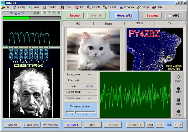
The
latest evolution in the transmission of high quality images is "Digital
SSTV." Although not actually Slow Scan Television, the name seems to
have stuck since the mode is used to send pictures in a similar
fashion. Popular softwares include DIGTRX and Easypal, which use the
DRM platform to send images by file transfer.
The
advantage over analogue SSTV, according to Paul Young (G0HWC), is the
error correction. "With error correction you get a perfect image IE
what is sent is what you receive "(Young). Another program currently
under development is KGSTV, which is not compatible with Easypal or
DIGTRX. KGSTV works by "mimicking" analog SSTV, but instead of scanning
an image line by line, KG scans the image in blocks of 16X16 pixels. 15
scan lines consist of 20 blocks of 16X16 pixels, that during
transmission, are compressed and digitally encoded one-by-one. The
program allows the use of two types of digital modulation - MSK (2
levels) and MSK (4 levels). Minimum Shift Keying (MSK), is an FSK phase
that continues where the frequency deviation is equal to half the
signalling rate in baud. The time it takes to send an image depends on
the mode chosen. KGSTV also allows compression to be adjusted, which
has obvious effects on the quality of images, especially JPEGs.
For
more information on
Digital SSTV, please click on the links below:
WSPR,
(pronounced "whisper"), stands for Weak Signal
Propagation Reporter.
It is an open source software tool that uses the transmission mode
MEPT-JT, written by Joe Taylor, (K1JT), of Princeton, New Jersey. WSPR
is designed for sending and receiving low-power transmissions to test
potential propagation paths on the MF and HF bands.
According
to amateur-radio-wiki.net, in MEPT transmissions, the "radio becomes a
beacon that transmits for just under 2 minutes." Normal transmissions
carry a station's call sign, maidenhead grid locator, and transmitter
power in dBm. Modulation is by narrow-band FSK. The program is said to
be able to detect and decode signals with a signal-to-noise ratio as
low as -28 dB in a 2500 Hz bandwidth. A nice feature about WSPR is that
"spots can be automatically downloaded to a central database: WSPRnet.org
and results can be shown on a large map."
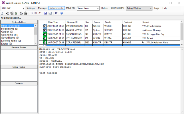
Winlink Express
is a global radio email client that supports a wide selection of
transceivers, TNC's, and multiomde controllers, the soundcard mode
WINMOR using the included WINMOR virtual TNC, HF PACTOR, SCS Robust
Packet, VHF/UHF AX.25 Packet, and direct telnet to CMS servers or RMS
Relay (for amateur radio High Speed Multimedia HSMM, Broadband Hamnet,
D-STAR DD mode, internet, and other TCP/IP networks).
Winlink
Express is designed to be easily used by single users with a single
call sign but it may also be used to simultaneously send and receive
mail with one or two tactical addresses or alternate Winlink accounts.
It supports a wide selection of transceivers, TNCs and multimode
controllers, the sound card modes WINMOR, Ardop, and VARA using virtual
TNCs, HF Pactor, SCS Robust Packet, VHF/UHF AX.25 packet radio, and
direct telnet to CMS servers or RMS Relay (for amateur radio High Speed
Multimedia [HSMM], Broadband HamNet, D-Star DD mode, internet, and
other TCP/IP networks).
Winlink Express is often used as a
client for emergency communications. It includes special features for
EmComm, such as HTML forms creation and compact, formless content
transport, plus a growing library of automatically-updated forms.
Amateur
Radio Wiki.net.
"WSPR."
<http://www.amateur-radio-wiki.net/index.php?title=WSPR>
24 December 2011.
Anderson,
Phil. (also Michael Huslig, Glenn Prescott, and Karl
Medcaff). "G-TOR
Background Research." Kantronics Corporation.
<http://mysite.ncnetwork.net/~nb6z/g-tor.htm> 9
March 2011.
Beischel, J. Duffy. "Digital
Modes Information Page." PP 1-4.
<http://wb8nut.com/digital> 9 March 2011.
Dorenberg,
Frank. "RTTY - Radio Teletype." Web article, and RTTY tape
image.
"Franks Ham Radio."
<http://www.nonstopsystems.com/radio/frank_radio_rtty.htm>
Ford, Steve. "The HF Tower of
Babel." QST Magazine.
January 2001. PP 50-53. ARRL Publishing. Newington, CT
Greenman,
M. "PSK Modes." FL DIGI Help Topics. PP 1-3.
<http://www.w1hkj.com/FldigiHelp-3.20/Modes/PSKdesc.htm>
9 March
2011.
Langner, John. "Slow-Scan
Television." 2003 ARRL Handbook. sec. 12.39. American Radio Relay
League. Newington, CT.
McMasters, Jim. "Meteor
Scatter." Audio file. <http://www.qsl.net/kd5bur> 9 March
2011.
Mills, Ernie. "Digital World
Homepage." Various Topics. <http://www.qsl.net/wm2u> 9
March 2011.
Wireless
Institute of Australia. "Radioteletype, RTTY."
<http://www.wia.org.au/members/digital/rtty>
23 March
2011.