   
Holiday
Edition
Volume
7, Issue 3
|
<< back
|
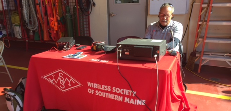
WSSM at the South Portland Fire Department Open House
South Portland,
ME
by
Tim Watson, KB1HNZ
On
Saturday, October 14th, WSSM members, including Rory McEwen KB1PLY,
Charlie Shepard W1CPS, and Tim Watson KB1HNZ, set up a display table
and a portable HF station during the annual South Portland Fire
Department Open House.
The event, which took place at the
Western Avenue Fire Station, featured fire trucks on display, including
a fully extended ladder unit, an ambulance, demonstrations of the jaws
of life, food, activities, and more.
The Cumberland County
Emergency Management Agency (CCEMA), and several local businesses also
had displays. There were lots of kids having fun, climbing in the
trucks, and the many families were enjoying the beautiful fall day.
The
WSSM team setup an HF radio, using a BuddiPole antenna, for on-air
activities, and made a good demonstration of the hobby for the curious
onlookers. There were also some other radios on display, including an
Icom IC706MKIIG, which is used during SOTA and other portable
operations, as well as some of the other equipment used, including SLA
batteries of various sizes. Intro to ham radio handouts and club
information was also available.
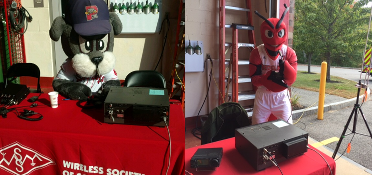
The highlights of the day occurred when mascots from two of the local sports teams stopped by to play a little radio.
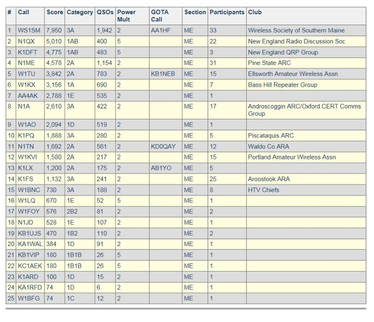
WS1SM #1 in Maine for 2017 Field Day
ARRL Field Day
by
Tim Watson, KB1HNZ
SCARBOROUGH,
ME - The 2017 Field Day results are in, and WS1SM took first in Maine
for the fourth consecutive year! Congratulations to everyone on our
team for a job well done!
WS1EC Participates in Maine and New Hampshire Simulated Emergency Tests
CCEMA Bunker, Windham,
ME
by
Tim Watson, KB1HNZ
WINDHAM, ME - On
Saturday, October 28th, the WS1EC and WX1GYX teams took part in the
Maine Simulated Emergency Test (SET), and on the following Saturday,
they were at it again, for the New Hampshire SET.
The
scenario for the Maine SET was an ice storm similar to the 1998 Ice
Storm. Among the concerns would be power outages, loss of land line and
cell phone communications, and loss of repeaters. Our plan, in addition
to communicating with the state EOC via HF, included establishing
communications between the CCEMA Bunker and all of the FEMA/Red Cross
shelters in Cumberland County, and relaying weather reports from each
location to NWS Gray. At the end of the day we were successful in
contacting each of the shelters, State EOC, NWS, and the Red Cross
chapter in Portland.
The reason for such an aggressive plan was
to identify which shelter locations would require something more than
an HT to reliably contact the CCEMA Bunker during a real activation.
During the exercise, we were able to identify three locations that need
more than 25 watts and an antenna with gain, to reliably
communicate.
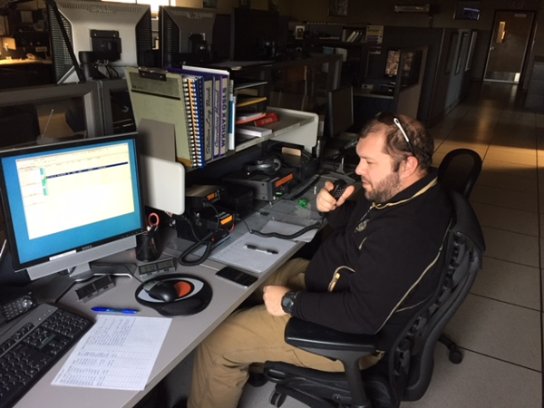 Eric Emery KC1HJK operates from NWS Gray during the New Hampshire SET Eric Emery KC1HJK operates from NWS Gray during the New Hampshire SET
The
SETs were used primarily as a training exercise for participants, as
they offered good practice of sending and receiving formal messages,
using NBEMS and Winlink, and providing familiarity with the ham
stations at both NWS Gray and the CCEMA Bunker.
Multiband Antenna Traps
Ham Radio Projects
by
Frank Kamp, K5DKZ
These
devices are called Traps, but they are actually more like frequency
sensitive switches. They are parallel resonant, high Q, tuned
circuits which provide a very high impedance at their frequency of
resonance.
An example of their use can best explain their
operation. Take, for example an 80/40 meter trap dipole. The
center section of this antenna is a normal 40 meter dipole of
conventional length. One end of each trap is connected to the ends of
this dipole. The other end of the trap is connected to additional
lengths of wire (typically 21 feet) to allow the complete antenna to
resonate on 80 meters.
The resonant frequency of the traps
should be the frequency you wish to use in the 40 meter band. The
additional 21 foot lengths of wire should be adjusted so that the
antenna resonates at your choice of frequency for the 80 meter
band. Note that each leg of the dipole is only a little over 50
feet long making it about 20 percent shorter than a full sized 80 meter
dipole.
On 40 meters, the traps have a very high impedance,
effectively disconnecting the two 21 foot lengths of wire needed for
80. On 80 meters, the traps act as loading coils permitting the
antenna to be shorter than a conventional 80 meter dipole.
The
80/40 meter trap dipole example will work on all bands (80, 40, 20, 15,
and 10), but will work most efficiently on 80 and 40. If this
sounds to good to be true (shorter antenna with multiple band
performance), there are some compromises to be considered. On 80
meters even a full sized dipole cannot provide an SWR of less than 2:1
across the entire band. On 40 meters, we have the same problem to
a lesser extent. A trap dipole exhibits an even narrower
bandwidth than a full sized antenna. Still, if your use of these
bands can be served with a 200khz to 250khz bandwidth, a trap dipole
can be a good solution.
Another compromise of a trap dipole is
the requirement for the traps. Conventional traps are constructed
of high voltage transmitting type capacitors and heavy B&W
miniductor stock. They are not particularly difficult to make,
but the parts are expensive and they are subject to drift in frequency
when exposed to adverse weather conditions. However, there is a
method of building traps that is very inexpensive, can withstand full
legal power limits, and is relatively stable under even the most
adverse weather conditions.
The 1988 ARRL Handbook alludes to
this method of trap construction but does not give any specific
data. I have built a set of traps using this method and would
like to share the information with anyone interested in homebrewing a
trap dipole.
My traps were built to be used in an 80/40 meter
dipole as in the example given. The same method of construction
can be used for other frequencies with the turns reduced to cover the
higher frequencies.
The method of construction alluded to in the
handbook uses a coil of coax to form the tuned circuit of the
trap. The shield of the coax forms the coil. The center
conductor of the coax on one end of this coil is connected to the
shield at the opposite end. This allows the capacitance between the
center conductor and the shield to act as the capacitance that
resonates the assembly.
Aside from the low cost, this method
reduces resistive losses in the coils to an absolute minimum. The
shield portion of the RG62AU coax I used is electrically equivalent to
using quarter inch copper tubing. The capacitor formed by this
assembly is capable of withstanding several thousand volts of RF
allowing the use of high power on 40 meters. Although I used
RG62AU, RG58 or RG59 would serve as well. RG8 may also be usable,
but it's stiffness might require a larger diameter coil form and may
result in a heavier assembly.
My traps were wound on two 6.5
inch long pieces of schedule 40 PVC pipe 1.25 inches O.D. I found
that 20.5 turns would resonate at 7.285 mhz, my chosen 40 meter
frequency.
Each end of the PVC pipe was prepared by drilling two
opposing holes in it about 0.25 inches in from each end. Solid
number 12 copper wire was inserted through these holes and bent around
thePVC to form a loop with the wire inside the pipe. These
terminations were used to attach the antenna wire as well as provide a
tie point for the coil of coax.
Each trap will require 80.5
inches (6.7 feet) of coax. Start with seven feet and trim it up
to the frequency you want in the 40 meter band. Each length of
coax is prepared by stripping about 2 inches of outer insulation from
each end. The shield is unbraided and twisted at each end.
The center conductor at one end is stripped of insulation for a length
of about 1 inch.
Start your winding by drilling a hole just
large enough to pass the coax through the PVC pipe. This hole
should be located about 0.5 inches in from the end of the pipe. A
close fit of thecoax through this hole will help secure the winding
until the holes are filled with epoxy.
Insert the end of the
coax that has the center conductor stripped through the hole and wrap
the shield of the coax around the number 12 wire at this end.
Solder the shield to the wire. Use a 50 to 100 watt iron and do it
quickly so that the heat will not travel up the braid to melt the
insulation to the center conductor. Let the soldered connection
cool completely before starting the winding.
Now wind about 22
turns of coax onto the pipe. I estimate that 22 turns will
resonate at the low end of the 40 meter band. If you are interested in
the higher portion of the band, stop at 21 turns. Remember, you
can always cut off coax to raise the frequency, but if you get too high
in frequency, your best bet is to start over with a new length of coax.
Mark
the pipe at the end of the winding and drill another hole in the pipe
at this location to pass the coax. The close fit of the coax into
this hole will keep the windings in place.
Prepare a length of
wire. Hookup wire #20, #18, #12, is adequate. Cut the wire
to 6.5 inches in length. Strip off 1.5 inches of insulation from
each end of the wire. Solder one end of the wire to the center
conductor of the coax at the end where you started your winding.
Pass the wire down through the center of the pipe and twist it's bare
end to the coax braid where you finished the winding.
Pull the
hookup wire through the center of the pipe so that the soldered bare
end of the coax center conductor is pulled down away from the soldered
coaxial braid at the end of the coil where you started the winding.
Now
you will need a grid dip meter to check the resonant frequency of the
trap. Don't rely on the grid dip meter's calibration. Use a
frequency counter or your communications receiver to verify the
frequency. (My homebrew grid dip meter doesn't even have a
calibrated dial. Only it's coils are marked as to frequency range
covered.) I found that by inserting the coil of the grid dip
meter about 1/8th inch into the end of the PVC pipe an easily
recognizable dip could be obtained. For your final frequency
check you may want to reduce the coupling between the dip meter's coil
and the trap. In my case I found a 50khz shift in frequency as I
reduced the coupling. The dip obtained at the reduced coupling is
the more accurate one. Also, make certain that your dip meter is
on the right frequency range and that you have the receiver tuned to
the fundamental frequency and not a harmonic. My grid dip meter had
enough output to register an S9 +20db at the receiver with the
receiver's antenna disconnected. Use the receiver's S-meter to
zero in on the dip meter's output when determining frequency or zero
beat as you would on an AM signal.
Your first frequency
measurement should fall somewhere in the low end of the 40 meter
band. If it doesn't, and if you did get a dip on the meter, you
may be too low in frequency. If so, cut off about two inches from
your winding and try again. In my case, I found that a one inch
reduction in coax length resulted in an approximate 50khz frequency
shift.
As you cut more and more coax from the winding, you will
need to drill additional holes in the PVC for proper termination of the
winding. The PVC is easily drilled. This cut-and-try method
requires a little patience, but it is very repeatable. My first
trap took me two hours to build. The second was done in 15
minutes.
The coax winding is tight and close spaced onto the PVC
form. After your final frequency check, trim the finished end of
the coax winding and solder the braid and the short length of hookup
wire to the #12 copper wire termination that you installed in the pipe
at that end.
That completes the trap. Now all you have to
do is build another one and solder the antenna wires to the copper wire
terminations at each end of each trap.
Note that the number of
turns required will only hold true for RG62AU coax. Other types
of coax may well be used, but the turns required may vary.
Initially,
I was a little concerned as to whether or not the end terminations I
used would hold the strain of supporting the traps. The
terminations have held through the weather conditions we have
experienced in the last two months. However, I would not
recommend using anything less than schedule 40 PVC pipe.
First published in the "Ham Distribution Net BBS" in December 1993.
Introduction to D-STAR
Digital Voice and Data
by
Tim Watson, KB1HNZ
For
December's meeting topic, Eric Emery KC1HJK, will make an Introduction
to D-STAR presentation. As a preview, we'll take a closer look at what
D-STAR is all about.
D-STAR,
which stands for Digital Smart Technologies for Amateur Radio, is a
digital voice and data protocol designed for amateur radio. It was
developed in the late 1990's by the Japan Amateur Radio League (JARL)
in an effort to find new ways to bring digital technology to amateur
radio. The original study was funded by Japan's Ministry of Posts and
Telecommunications, and administered by the JARL.
Digital Voice (DV) and Digital Data (DD)
D-STAR
involves the transfer of both voice and data via digital encoding over
the 2 m (VHF), 70 cm (UHF), and 23 cm (1.2 GHz) amateur radio bands.
There is also an interlinking radio system for creating links between
systems in a local area on 10 GHz, which allows emergency
communications oriented networks to continue to link in the event of
internet access failure or overload.
The
Digital Voice portion of D-STAR uses Advanced Multi-Band
Excitation (AMBE) to compress the voice for transmission. AMBE is
implemented in the proprietary AMBE-2000 or AMBE-2020 chips which
are found within every D-STAR radio. Voice audio is encoded as a 3600
bit/s data stream, with 1200 bit/s FEC, leaving 1200 bit/s for an
additional data "path" between radios utilizing DV mode. On air bit
rates for DV mode are 4800 bit/s over the 2 m, 70 cm and 23 cm bands.
In addition to digital voice mode (DV), a Digital Data (DD) mode can be
sent at 128 kbit/s only on the 23 cm band. A higher-rate data protocol,
currently believed to be much like ATM, is used in the 10 GHz "link"
radios for site-to-site links.
There are only a handful of
D-STAR repeaters in Maine, and some areas have no coverage at all, but
that doesn't mean that you can't get on the air and have fun with the
mode. If you have a D-STAR capable radio and no repeater nearby, you
can make use of a D-STAR hotspot, such as a D-VAP dongle, or SharkRF,
and if you have no radio at all, you could use a DV Dongle to access
the network.
For more information about D-STAR, including links to additional resources, click here to visit our Intro to D-STAR page.
DX
News
October 18 - March 20
by
Tim Watson, KB1HNZ
The
Summer seemed a little quiet as far as DXpeditions go, with a few
interesting ones such as Greenland OX3LX, in late August and Fernando
de Noronha PY0F in September, but it began to pick up in October, with
several announced DXPeditions, including the HD8M activation of the
Galapagos, the much anticipated 3C0L DXxpedition to Annobon Island, and
OJ0JR (Market Reef). Some current DXPeditions include J5T (Guinea
Bissau), which is about to end on the 26th, and the TO2SP expedition to
St. Barthelemy, which is about to end on the 30th.
For more information about upcoming announced
DXpeditions, click here for the latest 425 DX News, by
Mauro
Pregliasco I1JQJ.
Upcoming DXpeditions
10/18
- 11/30
11/02 - 12/01
11/04 - 11/28
11/07 - 12/04
11/13 - 11/26
11/15 - 11/30
11/16 - 11/30
11/23 - 12/12
12/03 - 12/08
12/15 - 12/17
01/01 - 01/31
01/10 - 01/23
01/13 - 01/21
01/21 - 01/27
01/25 - 03/14
02/01 - 02/07
02/23 - 03/16
03/02 - 03/15
03/02 - 03/19
03/10 - 03/17
03/10 - 03/20
|
H44MS
3XY3D
3B8HC
5H3DX
J5T
9X2AW
TO2SP
3B9HA
XW4ZW
6V1A
RI50ANO
6Y6J
ZF2PG
J88PI
3Y0Z
P29VXG
3D2EU
XR0TD
YJ0GB
TX5X
9M0W
|
Solomon Islands
Guinea
Mauritius
Tanzania
Guinea Bissau
Rwanda
St. Barthelemy
Rodrigues I
Laos
Senegal
South Shetland Is
Jamaica
Cayman Is
St. Vincent
Bouvet I
Papua New Guinea
Rotuma
Easter I
Vanuatu
French Polynesia
Spratly Is
|
By DL2GAC, from Malaita I (IOTA OC-047); 160-6m; SSB
By F5OZC, from Kassa I (IOTA AF-051); 80-10m; mainly CW
By HB9ARY, from Pointe aux Sables; 80, 20, 17, 15, 12m; focus on 80m CW
By NK8O; 40-6m; mainly CW; QSL via NK8O direct and eQSL
By I1HJT and others; fm Bubaque I (IOTA AF-020); 160-10m; CW, SSB
By DF2QO, from Kigali; CW, SSB, RTTY, FT8; QSL also OK via M0OXO
By SP3CYY and others; 160-10m; CW, SSB, RTTY
By G0CKV; focus on low bands; holiday style expedition
By K4ZW; focus on low bands; QSL also OK via K1SE
By 6W7JX, and others, from Goree I (IOTA AF-045); HF; CW, SSB
By UA1OJL, from Belligshaisen Station; HF; QSL also OK via RN1ON
By JA3HJI and others; 160-6m; CW, SSB and digital
By K8PGL, from Grand Cayman I (IOTA NA-016); 160-10m; SSB
By GW4DVB, from Palm I (IOTA NA-025), FK92ho; 40-6m; mainly SSB
By Ey8MM and others; 160-10m; tentative dates
By JA1XGI, from Rabual, New Britain I (IOTA OC-008); 160-30m; CW
By 3D2AG and others; 160-10m; CW, SSB, and digital
By DH8WR and others; 160-10m; CW, SSB, RTTY, FT8
By G7VJR, from Epule, Efate I (IOTA OC-035); HF; multiple modes
By W0ZRJ, from Tahiti (IOTA OC-046); mainly CW, some SSB and JT9
By YT1AD and others; 160-6m; CW, SSB, and digital
|
SKYWARN Recognition Day is December 2nd
2017 SKYWARN Recognition Day is December 2nd, from 0000-2400 UTC.
SKYWARN
Recognition Day was developed in 1999 by the National Weather Service
and the American Radio Relay League. It celebrates the contributions
that volunteer SKYWARN radio operators make to the National Weather
Service. During the day, SKYWARN radio operators visit NWS offices and
contact other radio operators across the world.
For more information about SRD, click here.
|
FOR
SALE
- Yaesu VX8GR multiband
handheld transceiver. Includes 2 batteries. $275. Contact: Kevin
Martel, at: kevinmartel@gmail.com
If
you have any items for sale, contact one of our members to have it
listed here, or send an email to: w1wmg@yahoo.com
with a brief description and contact information.

WinterFest 2018 - Location: Whitman, MA. Type: ARRL Hamfest. Sponsor: Whitman Amateur Radio Club. Click here to learn more.
|
New York / Long Island Section Convention - Location: Brookville, NY. Type: ARRL Convention. Sponsor: Radio Central Amateur Radio Club. Click here to learn more. OCARC Annual Hamfest - Location: Middletown, NY. Type: ARRL Hamfest. Sponsor: Orange County Amateur Radio Club (OCARC). Click here to learn more. Long Island Hamfest and Electronics Fair - Location: Hicksville, NY. Sponsor: Long Island Mobile Amateur Radio Club. Click here to learn more.
|

If you
have any items for trade, contact one of our members to have it listed
here, or send an email to: w1wmg@yahoo.com with a brief
description and contact information.

If
you offer any ham radio related services, for example, if you repair
meters or radios, build your own transmitters, make QSL cards to order,
or rebuild microphones, you may list these services here.

I f
there are any items you may be looking for, use this space to get the
word out. Just send an email to w1wmg@yahoo.com, or mention it at
an upcoming meeting. |
All
advertisements are listed for FREE. Advertising shall pertain to
products and services which are related to amateur radio. No
advertisement may use more than 40 words. Please send a description of
items for sale, wants, or services to Thom Watson at w1wmg@yahoo.com,
or bring it to an upcoming meeting of the Wireless Society of Southern
Maine. All ads will be printed one time, unless renewed.
|
Page
2
|